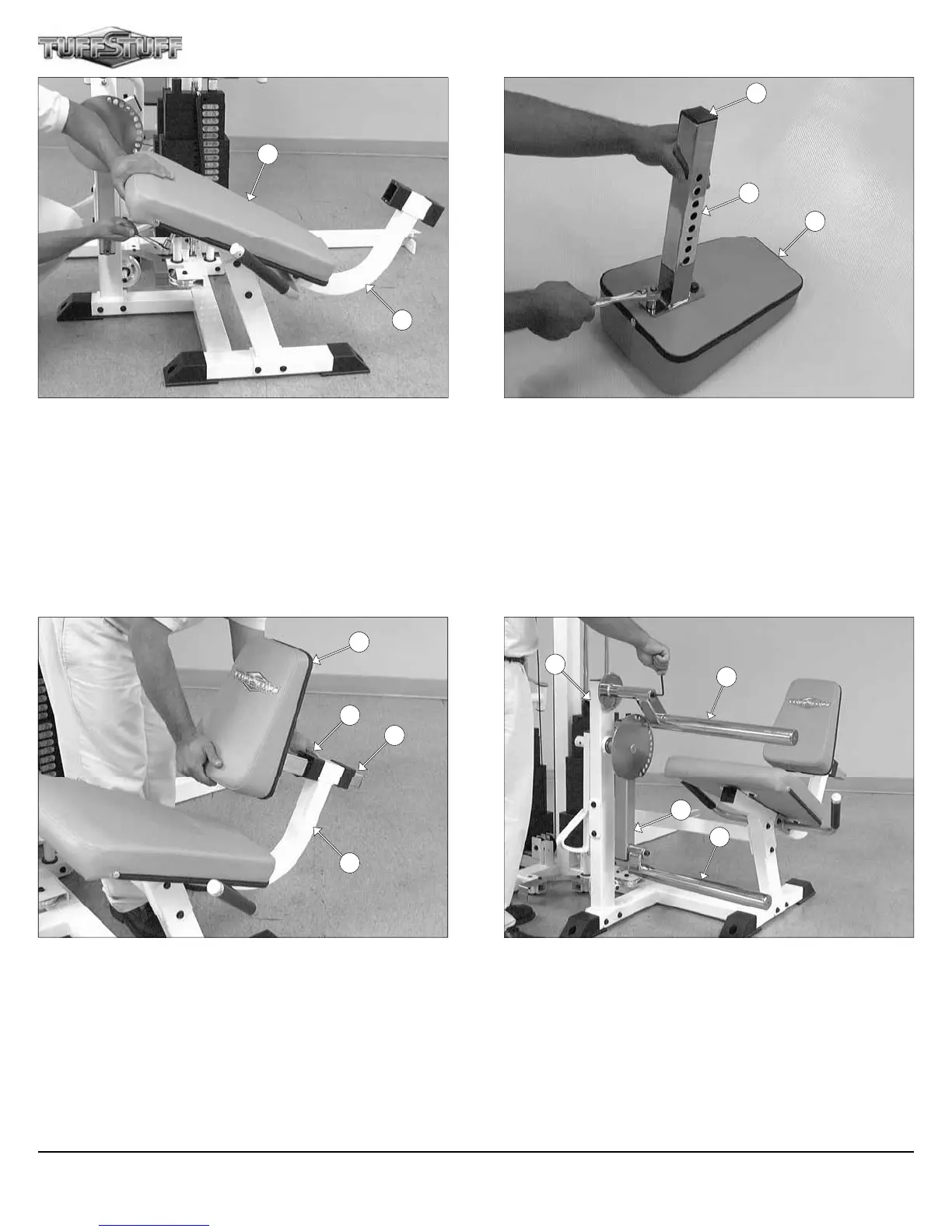
FIG. 57 Attach Leg Extension Seat Pad (#29) to the Leg Extension
Seat Frame (#28) using four Hex Head Cap Screws 3/8-16 X 1 1/4
(#96), and four Flat Washers SAE 3/8” (#93).
FIG. 59 Insert the assembled Back Pad Adjustable Tube (#3) to the
Leg Extension Seat Frame (#28).
FIG. 58 Using a rubber mallet, insert one Plastic Insert Cap 1 3/4”
Sq. (#123) into the tube-end of the Back Pad Adjustable Tube (#3).
Next, attach the Back Pad Adjustable Tube (#3) to the Leg Exten-
sion Back Pad (#29) using two Hex Head Cap Screws 3/8-16 X 1 1/4
(#96), and two Flat Washers SAE 3/8” (#93).
FIG. 60 Next, attach the Top Adjustable Leg Holder Tube (#48) to
the Leg Extension Front Frame (#27) using one Button Head Socket
Cap Screw 3/8-16 X 1 (#71), one Split Lock Washer 3/8” (#152), and
one Chrome Washer 3/8 X 1 1/2 (#74). Next, attach the Swivel Foam
Roll Tube (#47) to the Pivot-Arm (#38) using one Button Head Socket
Cap Screw 3/8-16 X 1 (#71), one Split Lock Washer 3/8” (#152), and
one Chrome Washer 3/8 X 1 1/2 (#74).
29
28
3
123
24
28
156
24
27
38
47
48
17
3
Apollo Modular Gym System (Base Unit)