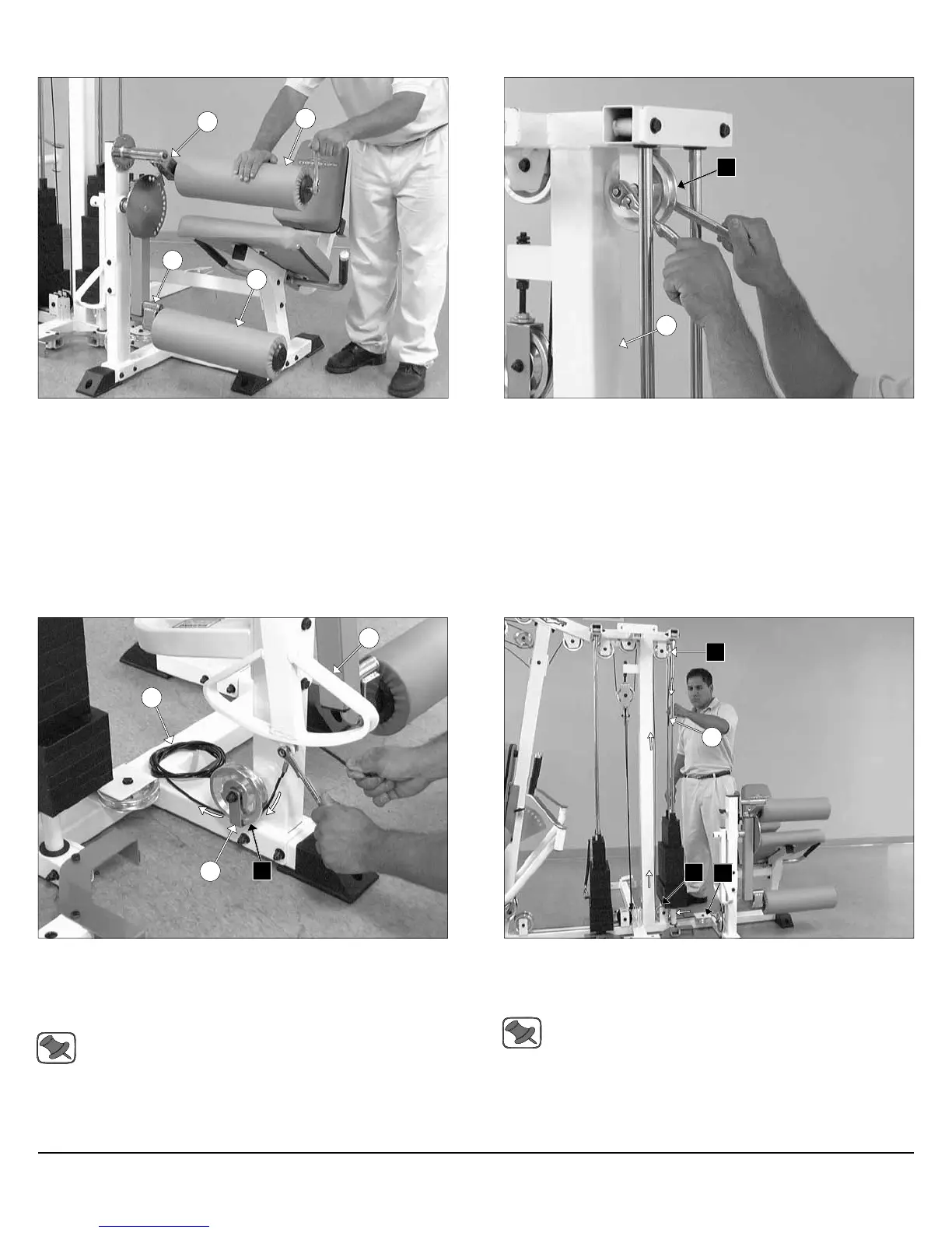
FIG. 61 Next, attach two Foam Rolls 2 X 5 1/2 X 18 (#14) to the Top
Adjustable Leg Holder Tube (#48) and the Swivel Foam Roll Tube
(#47) using two Button Head Socket Cap Screws 3/8-16 X 1 (#71), two
Split Lock Washers 3/8” (#152), and two Aluminum Washers 3/8 X
2.584 OD (#68).
FIG. 63 Attach the looped-end of the Leg Extension Cable (#26) to
the bracket of the Actuator Arm (#1) using one Shoulder Bolt 3/8 X 3/4
(#144), and one Nylon Insert Lock Nut 5/16-18 (#120). Next, route the
Leg Extension Cable (#26) under the Pulley 4 1/2 Rd. (#67-Labeled
C1).
Note: Refer to the Cable Mapping Diagram on fold-out page 26
for further detailed illustration of the Leg Extension Cable (#26)
routing.
FIG. 62 Attach a Pulley 4 1/2” Rd. (#67-Labeled C4) to the Weight
Stack Frame (#53) pulley bracket using one Hex Head Cap Screw 3/8-
16 X 1 3/4 (#97), two Flat Washers SAE 3/8” (#93), and one Nylon In-
sert Jam Lock Nut 3/8-16 (#118).
FIG. 64 Continue routing the Leg Extension Cable (#26) around the
Pulley 4 1/2 Rd. (#67-Labeled C2). Next, route under the Pulley 4 1/2
Rd. (#67-Labeled C3), and then up and over the Pulley 4 1/2 Rd. (#67-
Labeled C4).
Note: Refer to the Cable Mapping Diagram on fold-out page 26
for further detailed illustration of the Leg Extension Cable (#26)
routing.
14
14
48
47
C4
53
8
1
26
C1
26
C4
C2
C3
18
Assembly Instructions
Apollo Modular Gym System (Base Unit)