EN
UNI 30 E 17261 - 561.228 7 - USE AND OPERATION
7
- Pag. 4/14
THIS MANUAL IS PROPERTY OF - ANY TOTAL OR PARTIAL REPRODUCTION IS STRICTLY FORBIDDEN
Cap.
• Start lever:
check that the dear lever (FIG.25-REF.1) is in the idle position (the machine has a two speed gear).
• Safety screw:
check that the safety screw (FIG.24-REF.2) that blocks the bodywork is regularly fixed.
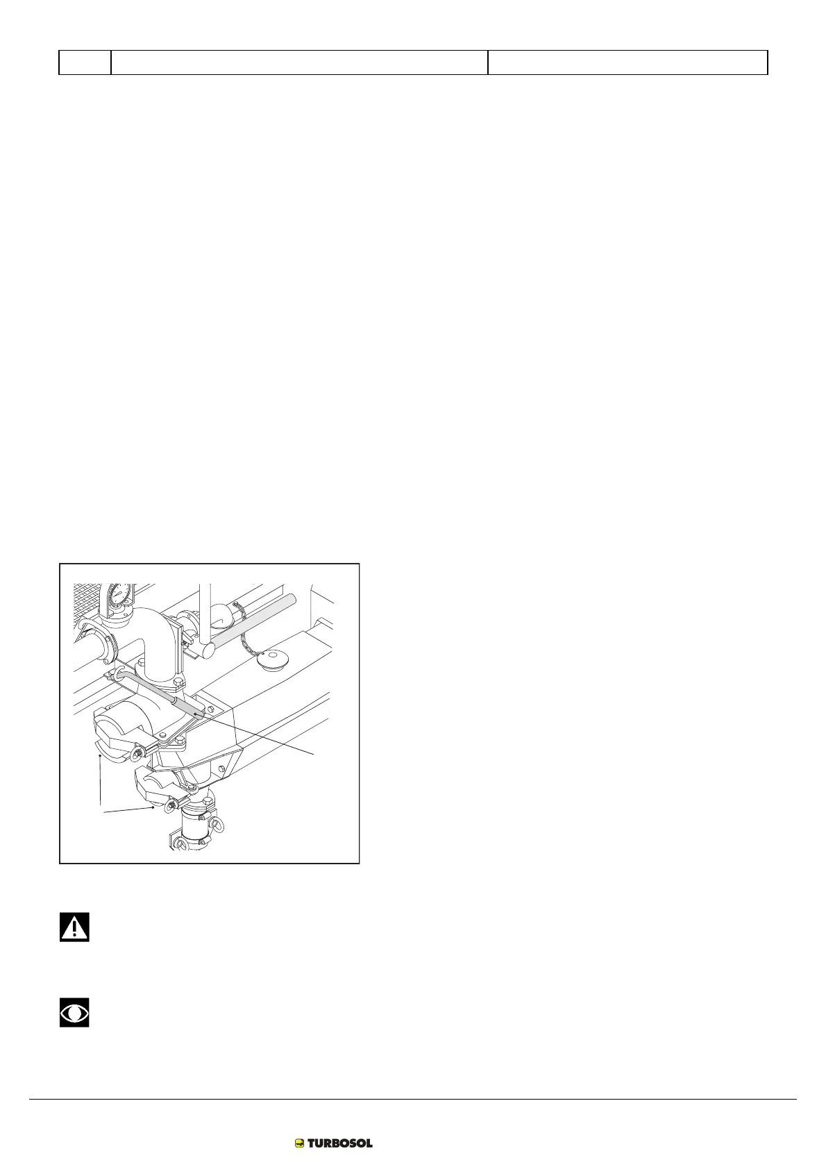
• Inspection caps:
make sure that the machine inspection caps (FIG.26-REF.1) dare perfectly blocked.
Perform this operation using the relevant spanner (FIG.26-REF.2) supplied with the plastering machine to tighten the stands by
acting on the ring nuts.
• Hopper safety grill:
red indicator on (FIG.27-REF.5) means that the grill on the hopper is not positioned regularly. During lifting of the grill, the
machine stops automatically through contact with the micro switch. At every stop induced by the safety sensors, take the
master switch (FIG.27-REF.2) to 0 (zero).
Version with mixer (EMF version)
• Mixer safety grill:
red indicator on (FIG.27-REF.5) means that the grill on the mixer is not positioned regularly. During lifting of the grill, the
machine stops automatically through contact with the micro switch. At every stop induced by the safety sensors, take the
master switch (FIG.27-REF.2) to 0 (zero).
1
2
FIG.26
After any repairs or maintenance make sure that all protection devices have been re-mounted and that no tool
has been forgotten inside the engine compartment or material hopper.
Tools or cloths forgotten inside the engine compartment can cause breakage of the cooling fan among other
things.