7
03
Installation
Manual 4804 Rev C p/n 004804 0000
SEALANT RECOVERY SYSTEMS
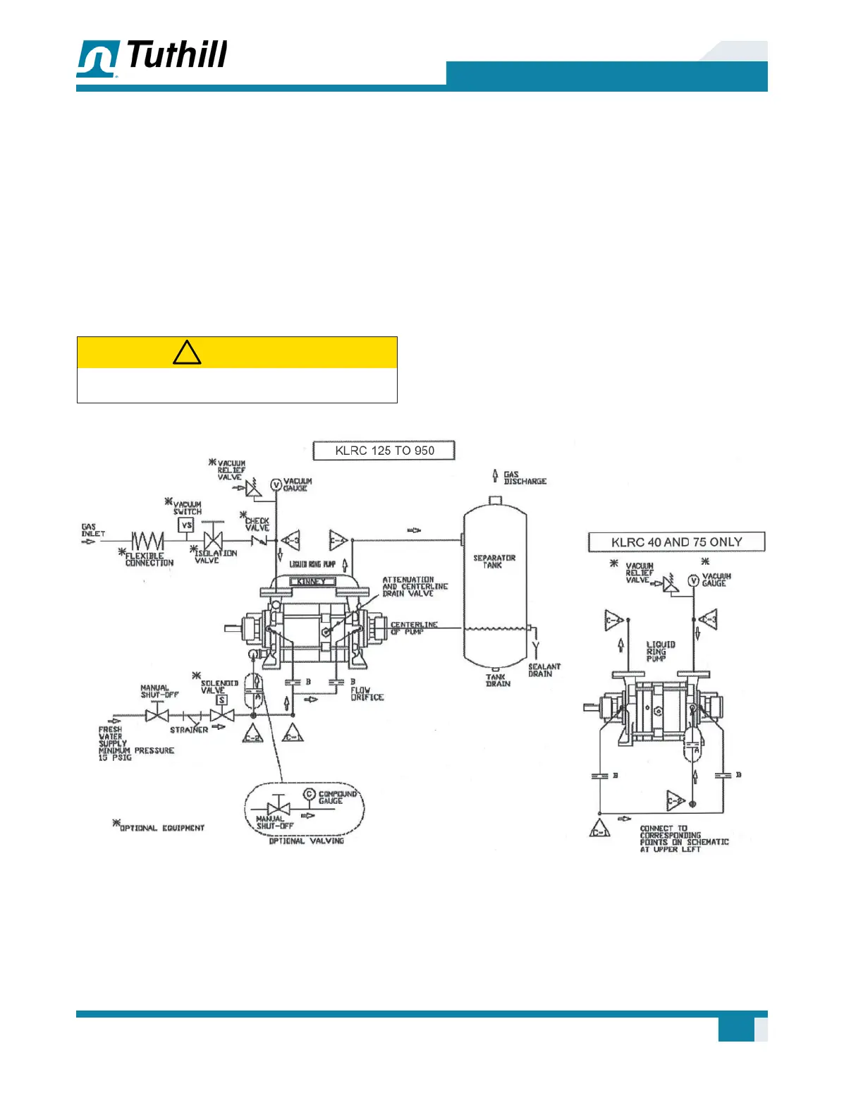
Figure 3-1 on page 7 through Figure 3-4 on
page 10 illustrate sealant con¿ gurations:
• Once-Through (Figure 3-1)
• Partial Recovery (Figure 3-2)
• Full Recovery with Circulating Pump
(Figure 3-3)
• Full Recovery without Circulating (Figure 3-4)
CAUTION
!
Do not run the pump dry.
ONCE-THROUGH RECOVERY
The once-through recovery system takes water
directly from the water supply through the
pump and discharges it directly through a gas/
liquid separator tank to an approved drain. This
arrangement is most common on small pumps,
in installations where water conservation is not a
factor, or where contamination of sealant is not a
factor. Optional valving arrangement is designed
to conserve sealant À ow and power, and when the
pump is operating at high pressure (low vacuum).
The optional system components are described on
page 12.
Figure 3-1 – Piping Schematic Once-Through Recovery System