15
5.4.2 LUBRICATION – INTEGRAL PRESSURE
5.4.3 OIL FILTER
The oil lter is self-contained. With every oil change, change the oil lter element and it’s shell gasket,
both available from Tuthill Vacuum and Blower Systems in Springeld, Missouri, or from any authorized
distributor or service center. Oil Filter Element (P/N 91999-1) Shell Gasket (P/N 12102-6)
CAUTION
Factory supplied lters are engineered to provide the proper restriction
in the oil lubrication system. Using lters other than those available from
Tuthill Vacuum & Blower Systems may result in lubrication problems and
possibly unwarrantable damage to the booster.
5.4.4 OIL PRESSURE ADJUSTMENT
The oil pressure on each unit has been preset at the factory during
the load testing. Generally the oil pressure should not require
adjustment once the unit is installed and in operation. Some
adjustment may be required due to the speed and oil temperature.
The oil pump itself has no adjustment, however, the oil by-pass
relief valve located in the oil feed line after the oil lter can be used
for the same purpose.
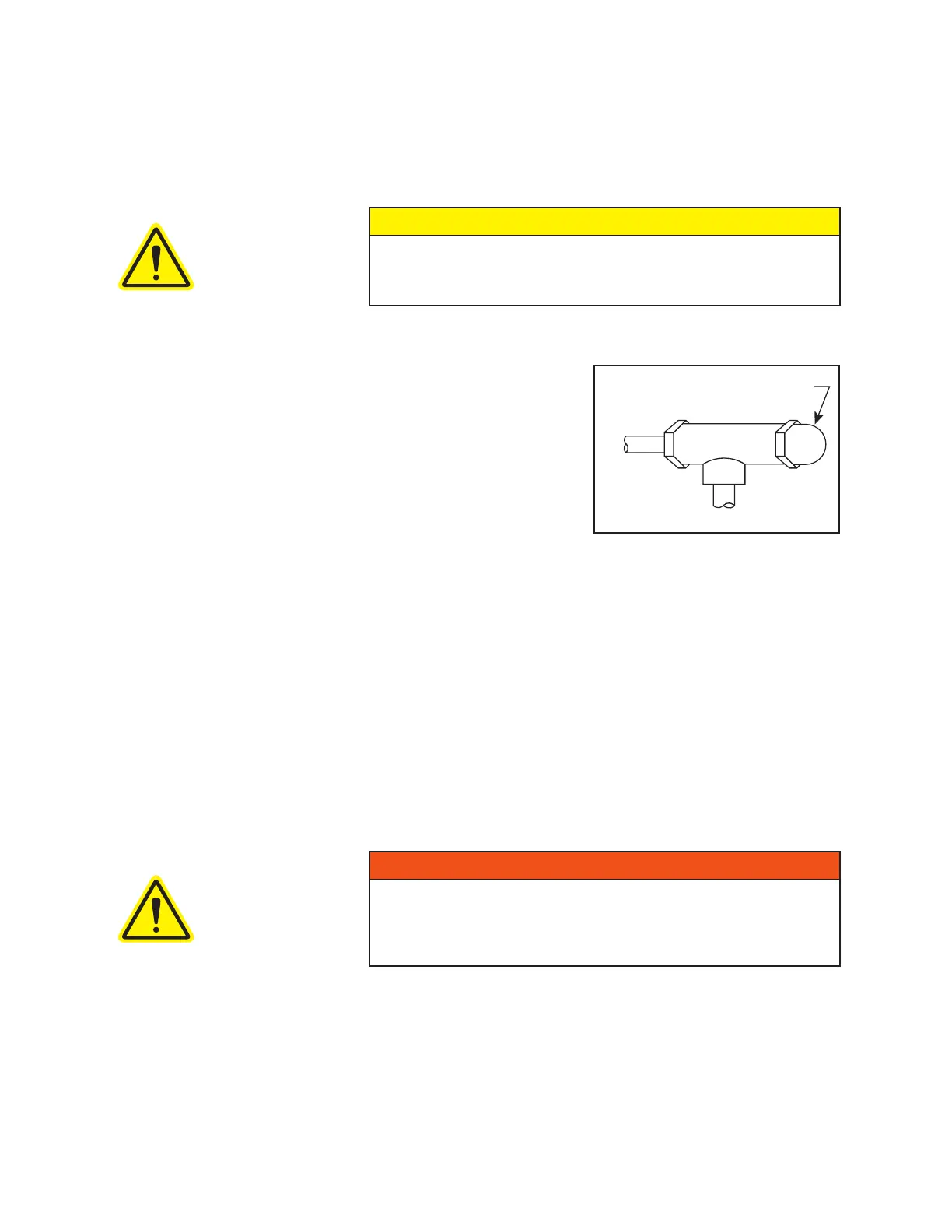
To adjust the unit to the proper oil pressure, remove the hex cap
shown in the image to the right. Loosen the lock nut and turn the
set screw clockwise to increase the pressure or counterclockwise
to decrease the pressure. Tighten lock nut and replace cap before reading oil pressure. Oil pressure may
vary between 5 psig and 30 psig. The unit’s oil system can operate satisfactorily at 1 psig, if necessary, and
still have sufcient ow. Always allow unit to reach operating temperature before adjusting the oil pressure
to the proper range. Set the oil pressure to 15 psig (103 kPa).
5.4.5 OIL COOLER
All versions are supplied with four-pass coolers. Either hole can be used for water inlet with no effect on
performance. For most applications, 2-5 GPM (7.5-20 L/min) of 60° F (15° C) water is generally sufcient.
Actual water usage will depend on operating conditions. Ideal oil temperature is 140°F (60° C) to 160° F
(72° C).
All standard coolers are designed for use with fresh water only. Do not use brackish or salt water. The liquid
to be cooled (oil) ows around the tubes and the cooling liquid (water) ows through the tubes.
WARNING
If the unit is to be located outside or in a building where ambient temperatures
can fall below freezing, then care must be taken to ensure the water or
liquid used for cooling does not freeze and damage the booster. Oil cooler
must be drained of liquid during downtime unless a re-circulating unit using
a glycol mixture has been installed.
Figure 6 - Pressure Relief Valve
HEX CAP
TO ADJUST
IN



 To Next Page