29
NOTE
NOTE: Two wave springs are necessary for the proper pressure on the
seal, but because of the pressure a tool as shown on page 23 is needed to
press the retainer ring into its groove. The tool will center the labyrinth seal
as it presses the retainer ring in place.
3. Series 19/86: Apply sealer to the O.D. of the lip seal. Install with lip facing upward. Tap in place with
installation tool shown on page 36. Apply grease to lip of seal.
Series 55/82/66/69: Install seal adapter (74). The adapter is used to anchor the stator portion of the
mechanical seal (54). To install the seal, grease both the O-ring and seal bore, then push the seal, by
hand, into the bore and against the seal adapter, making sure the two dimples on the bottom of the
seal case are aligned with the holes in the seal adapter. Clean surface with soft tissue and acetone.
NOTE
Never drive mechanical seal or seal tool with any type of hammer. This
could result in damage to the carbon or its ability to properly seal.
8.2.2 GEAR END ASSEMBLY
4. Place non-drive end plate on 6” × 6” blocks with the
solid side up. The end plate must be blocked up so
rotor shafts will not touch oor when they are installed.
Grease and install O-ring (176) in end plate groove.
Install housing (3) making sure dowel pins are in
place. Do not bolt in place at this time.
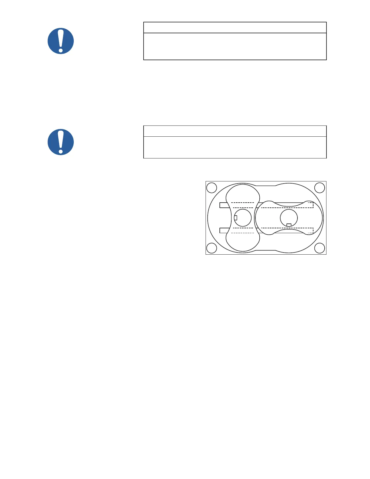
5. Lay two pieces of steel approximately 2” × 2” × 1/8”
thick at the bottom of the housing as shown in Figure
9 with the end (long shafts) up. The rotor lobes will
be above the end of the housing which is necessary
when assembling this end.
6. Grease and install O-ring (176) in groove of gear end
plate. Use sufcient grease to hold it into place when the end plate is turned over.
7. Install the end plate on the rotors and housing. The end plate will rest on the ends of the rotor lobes,
and there will be a space between the housing and the plate. Install all cap screws (301) and tighten
end plate to housing until tight.
8. Use six cap screws (301) equally spaced and secure non drive end plate against shims at bottom end
of rotors. Do not torque these bolts.
9. Grease O-ring (331) and start onto rotor shaft.
Series 19/86: Start sleeve (239) over shaft (larger diameter down) while forcing O-ring into step at
the bottom of the sleeve. Slide sleeve down the shaft until seated. You may encounter interference as
the sleeve passes through the PTFE rings. Tap sleeve with mallet to seat if necessary.
Series 55/82/66/69: Grease internal O-ring of mating ring portion of seal (Assemble mating ring over
sleeve (236) with lapped surface down. Slot in mating ring must line up with pin in sleeve and be ush
with top of sleeve when properly installed. Clean lapped surface of mating ring with soft tissue and
acetone. Lubricate surface and start sleeve over rotor shaft while forcing O-ring into step at bottom of
sleeve. Carefully slide this assembly down the shaft until seated.
10. Coat the rotor shaft with an anti-seize lubricant and press the bearing (9) on the shaft. The bearing
manufacturer numbers and/or an acid dot (inner race) should be up or toward the gears. Use the same
plates used to disassembly and a sleeve to press on the inner race of the bearing when installing.
11. Loosen cap screws holding non-drive end plate to housing then install bearing retainer rings (14) and
secure with cap screws (30). At this time check clearances between the rotor lobes and gear end plate.
See page 34 for the correct gear end clearances. If clearances are not within specications, recheck
parts to nd cause of improper clearances before proceeding. Retighten the cap screws on the non-
drive end but do not torque at this time.
DRIVE
DRIVEN
Figure 9 - Rotors in Housing



 To Next Page