19
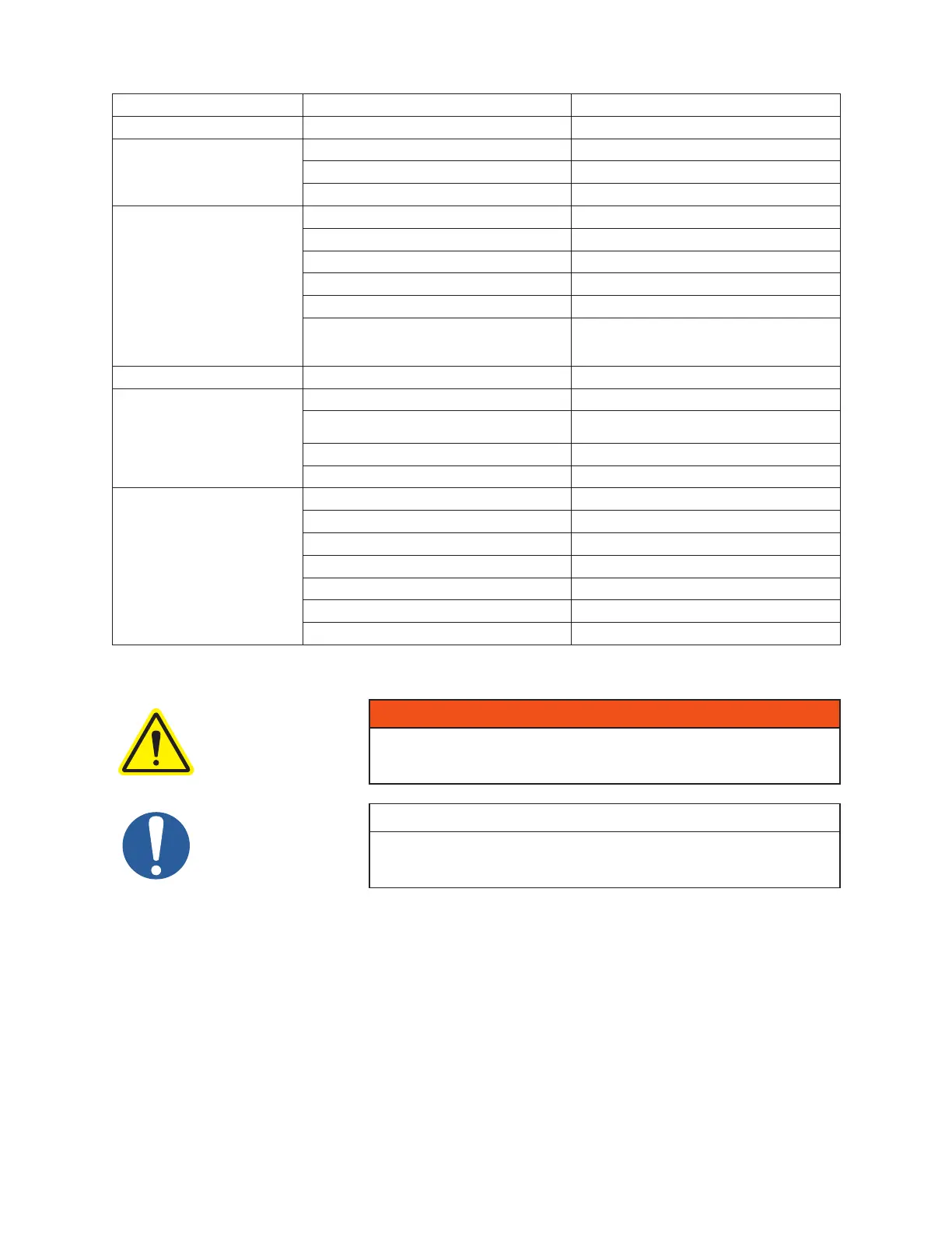
5.6.3 V-BELT TROUBLESHOOTING
PROBLEM POSSIBLE CAUSES SOLUTION
Belts slip (sidewalls glazed) Not enough tension Replace belts; apply proper tension
Drive squeals
Shock load Apply proper tension
Not enough arc of contact Increase center distance
Heavy starting load Increase belt tension
Belt(s) turned over
Broken cord caused by prying on sheave Replace set of belts and install correctly
Overloaded drive Redesign drive
Impulse loads Apply proper tension
Misalignment of sheave and shaft Realign drive
Worn sheave grooves Replace sheaves
Excessive belt vibration
Check drive design
Check equipment for solid mounting
Consider use of banded belts
Mismatched belts New belts installed with old belts Replace belts in matched sets only
Breakage of belt(s)
Shock loads Apply proper tension; recheck drive
Heavy starting loads
Apply proper tension; recheck drive
Use compensator starting
Belt pried over sheaves Replace set of belts correctly
Foreign objects in drives Provide drive guard
Rapid belt wear
Sheave grooves worn Replace sheaves
Sheave diameter too small Redesign drive
Mismatched belts Replace with matched belts
Drive overloaded Redesign drive
Belt slips Increase tension
Sheaves misaligned Align sheaves
Oil or heat condition Eliminate oil. Ventilate drive.
5.7 MOTOR AND ELECTRICAL CONNECTIONS
WARNING
The motor and connections shall be protected to assure that product and
environmental condensation does not come in contact with the electrical
connections.
NOTE
It is the responsibility of the installer to assure that the motor is in compliance
with the latest edition of IEC 60204-1 and all electrical connections
performed per IEC 60204-1, this includes over current protection.
Wire the motor and other electrical devices such as solenoid valves and temperature switch to the proper
voltage and amperage as indicated on the nameplate of each component being wired. Turn the blower by
hand after wiring is completed to determine that there are no obstructions and if the blower turns freely;
then momentarily start the blower to check the direction of rotation. Figure 2 shows direction of air ow in
relation to rotor rotation. The air ow direction can be reversed by reversing the appropriate motor leads.
 Loading...