Operator’s Manual 2023 Rev G p/n 2023
9
04
Installation
T855 / T855RS / T1055
VENT HOLES
Each transport blower is supplied with 4 vent plugs
that should be installed in the top four vent holes
once the nal mounting orientation of the blower is
determined.
Another option (not included), depending on
mounting bracket space, is to use 90° elbows with
or without exible tubing. If you choose to use vent
plugs, then follow the subsequent instructions. The
exact plug location will vary based on the mounting
position.
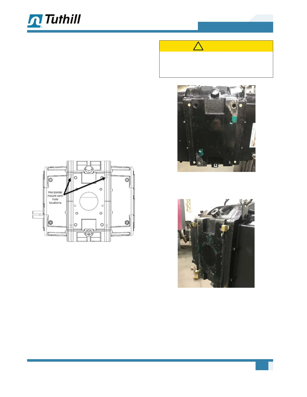
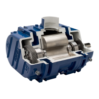
The image below shows one option for the vent
hole locations on a horizontal airow mount.
Figure 4-2 – Mounting Configuration
In this mounting conguration (See Figure 4-2)
the four holes (two are shown and two are on the
opposite side top) could have plugs added to them.
This would leave the four holes on the bottom of
the unit open or 90° 1/8" NPT elbows that face
down.
Four vent holes should always be open to air. You
can plug all the holes on the bracket side, then use
four 90° elbows on the non‑bracket side (horizontal
mount). Or you can plug two on each end plate at
the top side and leave two on each end plate at the
bottom open.
CAUTION
!
Never plug all the vent holes or serious damage to
seals and bearings will result. Four vent holes (two
per side or all four on one side) must always be open.
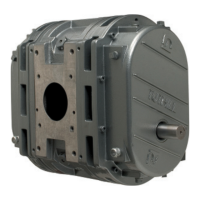
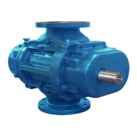
Figure 4-3 – Alternate plug configuration: Horizontal
mount with holes plugged on the bracket side
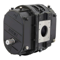
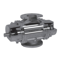
Figure 4-4 – Alternate plug configuration: Horizontal
mount with street elbows