Note: fm: measured frequency, [Hz]
4. HANDLER INTERFACE (available for 200kHz model only)
The HANDLER interface is used to output comparator results to industrial computer (IPC), so as to realize
automatic comparator test.
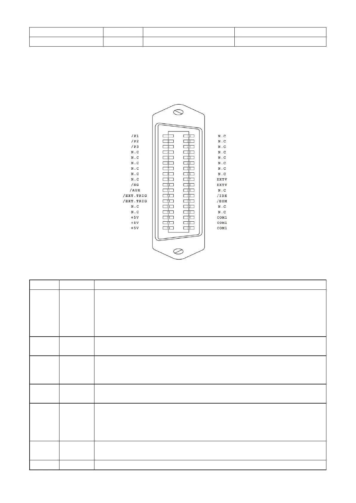
4-1. Pin Definition
Fig.4-1 Pin definition
Comparator result output.
All signals are collector outputs with built-in pull-up resistor. Pul-up power source can
be internal +5V power source or exteran power source EXTV (default at EXTV).
Resistance of the built-in pull-up resistor is 4.7kΩ.
Rising edge of this signal triggers measurement. Pulse width≥1μs. Low level drive
current approx. 5-10mA.
Internal +5V power output: Normally it is not recommended to use internal power
source. If the internal power source must be used, please make sure the signal’s
current is less than 0.3A and ensure the signal is well shielded from interference.
External DC power source input for comparator signal.
If using internal +5V power source, please reset the internal jumper connection.
/IDX is valid after A/D conversion is finished.
When the signal is valid, the automatic tester will allow the next component to move
into measuring position. The currently measured result will be output when /EOM is
valid.
End Of Measurement: the signal is valid when the measured results and comparing
results are valid.
Reference ground for external power source EXTV.
 Loading...