16 16
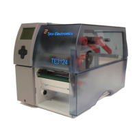
4.4 Setting the Feed Path of the Transfer Ribbon
Transferribbonwrinklingcanleadtoprintimageerrors.Transferribbondeectioncanbeadjustedsoastoprevent
wrinkles.
Notice!
The adjustment is best carried out during printing.
Fig. 11 Setting the feed path of the transfer ribbon
Readcurrentsettingonthescale(1)andrecordifnecessary.
Turnscrew(2)withAllenkeyandobservethebehavioroftheribbon.
In the + direction, the inner edge of the ribbon is tightened, and the outer edge is tightened in the - direction.
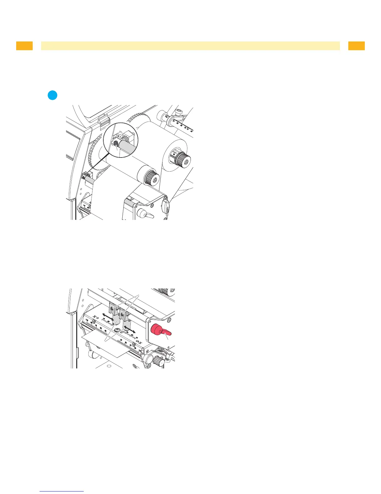
4.5 Setting the Head Locking System
Fig. 12 Setting the head locking system
Theprintheadispushedonviatwoplungers(1).Inthebasicsettingtheplungersaresetinthemiddleofthe
printhead retainer. This setting can be used for the most applications.
If the print density decreases in the outer areas when using very large media, the plungers can be displaced :
Turnlever(3)clockwisetolocktheprinthead.
Loosenthreadedpins(2)attheplungers(1)withAllenkey.
Displaceplungerssymmetricallyasnecessarymaximaltothescalevalue70.
Tightenthethreadedpins(2).
1.
2.
1.
2.
3.
4.
4 Loading Material