EQUIPMENT: T1200
PUBLICATION: 19A-4-O
ISSUE No. & DATE: 3 06/09
© 2006 Tyco Safety Products PAGE 5 of 13
Registered Company: Thorn Security Ltd. Registered Office: Dunhams Lane Letchworth Garden City Hertfordshire SG6 1BE
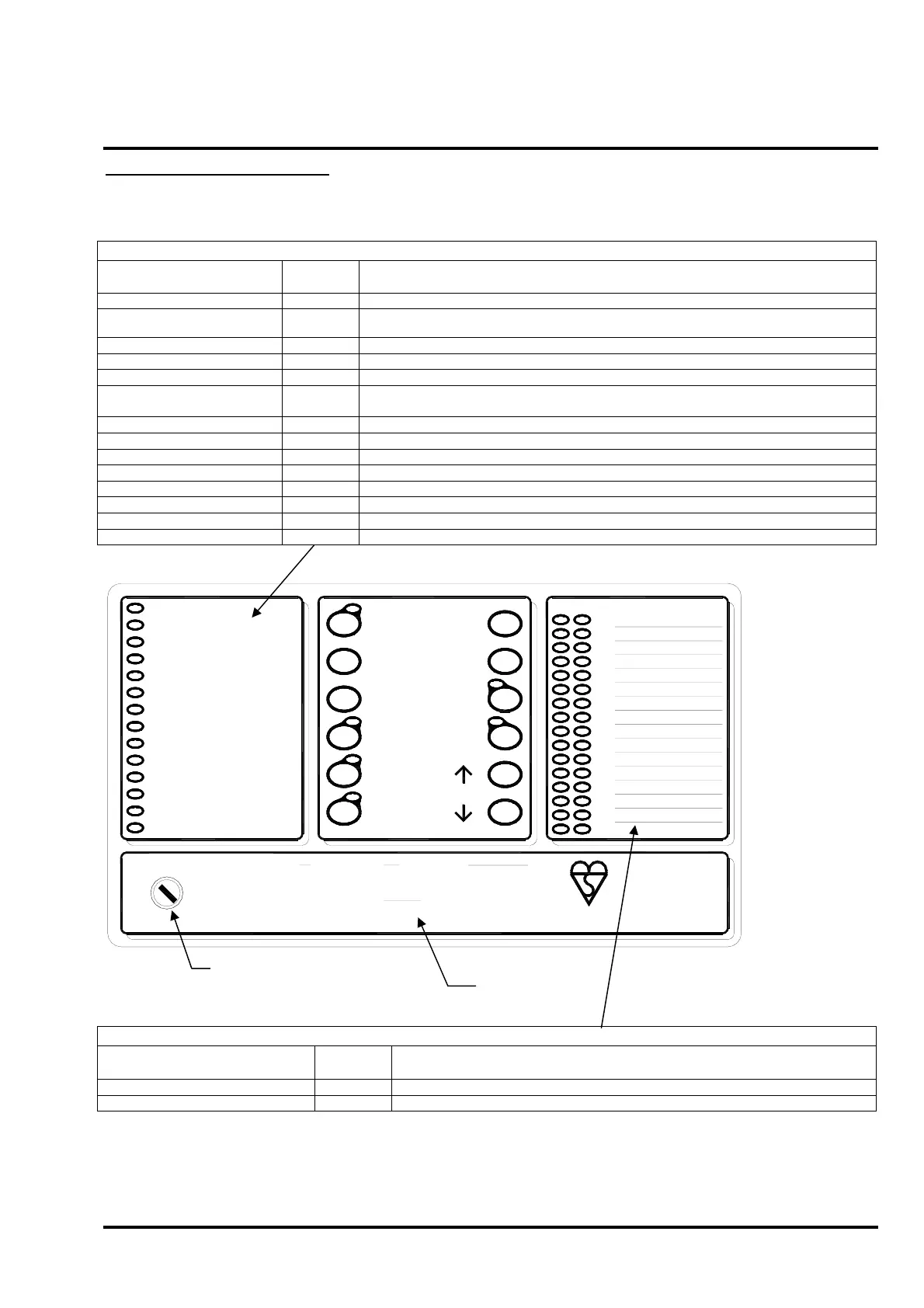
3. T1200 User Indications
This section gives an overview of the functions available to the end user.
3.1 User Indications
General Indicator Section
Indicator Description
Indication
Colour
Operating Condition
Power Supply On Green Illuminates Steady for Mains or Standby power On.
Fire Red
Flashes on any new fire alarm condition, changing to a steady indication on operation of Silence
Alarms.
Fire Output Active Red Illuminates Steady when the Fire Output is active.
General Fault Yellow Flashes for any fault condition.
Power Supply Fault Yellow Flashes for mains or standby power supply/charge fault
System Fault Yellow
Illuminates Steady to indicate Microcontroller or Memory Failure.
Flashes to indicate Engineer’s Configuration Mode active.
Earth Fault Yellow Flashes for any positive or negative power supply earth fault.
Fuse Failed Yellow Flashes for any auxiliary supply fuse failure.
Repeater Fault Yellow Flashes for any Repeater fault or repeater communication fault.
Sounder Fault/Disabled Yellow Flashes for any sounder fault. Steady for sounders disabled.
Sounder Test Yellow Illuminates Steady while sounder walk test is active.
Fire Protection Fault/Disabled Yellow Flashes for a fault on the Fire Protection Output. Steady when Fire Protection Output is disabled.
Fire Output Fault/Disabled Yellow Flashes for a fault on the Fire Output. Steady when Fire Output is disabled.
Fault Output Fault/Disabled Yellow Flashes for a fault on the Fault Output. Steady when Fault Output is disabled.
1.
2.
3.
4.
5.
6.
7.
8.
9.
10.
11.
12.
13.
14.
15.
16.
01
ZONE LOCATION
FIRE
POWER SUPPLY ON
POWER SUPPLY FAULT
SYSTEM FAULT
GENERAL FAULT
EARTH FAULT
FUSE FAILED
REPEATER FAULT
FAULT OUTPUT FAULT/DISABLED
SOUNDER FAULT/DISABLED
SOUNDER TEST
FIRE PROTECTION FAULT/DISABLED
FIRE OUTPUT ACTIVE
FIRE OUTPUT FAULT/DISABLED
BUZZER
SILENCE
RESET
ENABLE
DISABLE
TEST
TEST DISPLAY
ALARMS
RESOUND
SELECT
ON/OFF
SELECT
SILENCE/
ALARM
MUSTER
FIRE
1. THE RED ZONE INDICATOR
WILL PULSE SHOWING THE
LOCATION OF THE FIRE.
2. CARRY OUT THE
REQUIRED FIRE DRILL.
3. TO SILENCE ALARMS
PRESS SILENCE ALARMS.
4. TO RESET FROM THE FIRE
CONDITION PRESS RESET.
FAULT
1. DETERMINE THE CAUSE OF
THE FAULT.
2. PRESS SILENCE BUZZER.
3. CALL YOUR SERVICE
ENGINEER.
SYSTEM FAULT
THE PANEL IS INOPERATIVE.
ARRANGE FOR ALTERNATIVE
FIRE DETECTION MEASURES.
DISABLEMENT AND TEST
1. PRESS SELECT ON/OFF.
THE LED WILL ILLUMINATE.
2. SELECT THE ZONE OR
OUTPUT USING
↑ AND ↓. THE
FAULT LED WILL PULSE.
3. PRESS DISABLE OR TEST.
4. TO RE-ENABLE, SELECT
THE ZONE OR OUTPUT AND
PRESS ENABLE.
OVERRIDE
DELAY
MODEL:
T1216
C.I.E. PRODUCTION PERIOD: 1
www.tycomarine.com
EN54-2: 1997
EN54-4: 1997
KM95744
Zone Location Indications
Indicator Description
Indication
Colour
Operating Condition
User Generated Zone Location Text Red Flashes when zone is in a fire condition, turning to steady on operation of Silence Alarms.
User Generated Zone Location Text Yellow Flashes when zone is in a fault condition. Illuminates steady when zone is disabled or in test.
Access Controls Keyswitch:
0 – Controls Locked
1 – Controls Unlocked
User Instructions