XPLR-AOA-3 - User guide
UBX-22006906 - R07 EVB-ANT-1 Page 17 of 46
C1-Public
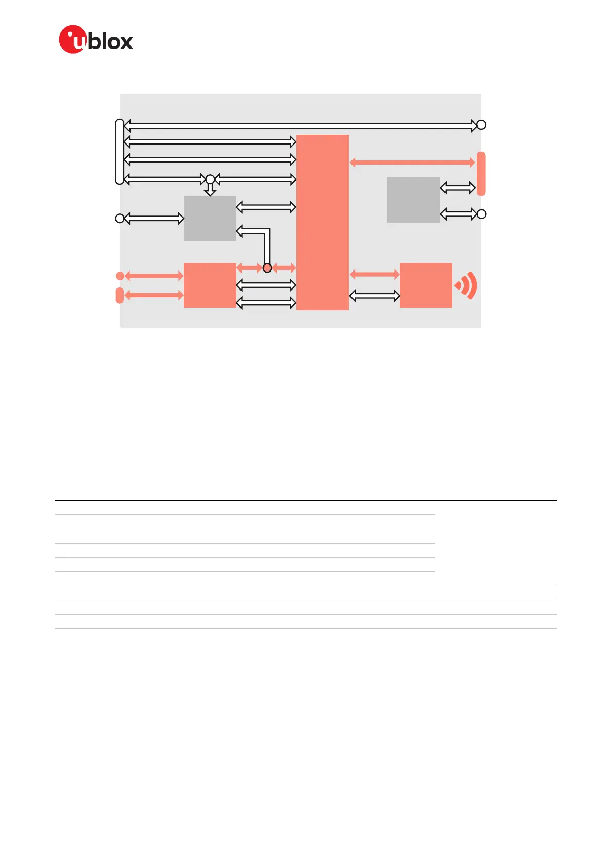
The highlighted areas in Figure 15 show the EVB-ANT-1 components involved in this use case.
Figure 15: EVB-ANT-1 components involved in antenna evaluation
High speed GPIOs from the onboard NINA-B411 module are broken out to a 20 pin (2x10), 2.54 mm
pitch header along with 5 V and 3.3 V power supplies. These GPIOs can be used to drive RF switches
that facilitate custom switching of the antenna array. The connector pinout is shown in Figure 16.
Table 1 shows the available signals on the antenna header. These signals are the same as those used
on the NINA-B411 hosted on ANT-B family antenna board. Access to these pins from the header pin
make it easier to test custom antenna boards.
 Loading...