XPLR-AOA-3 - User guide
UBX-22006906 - R07 C209 tag Page 24 of 46
C1-Public
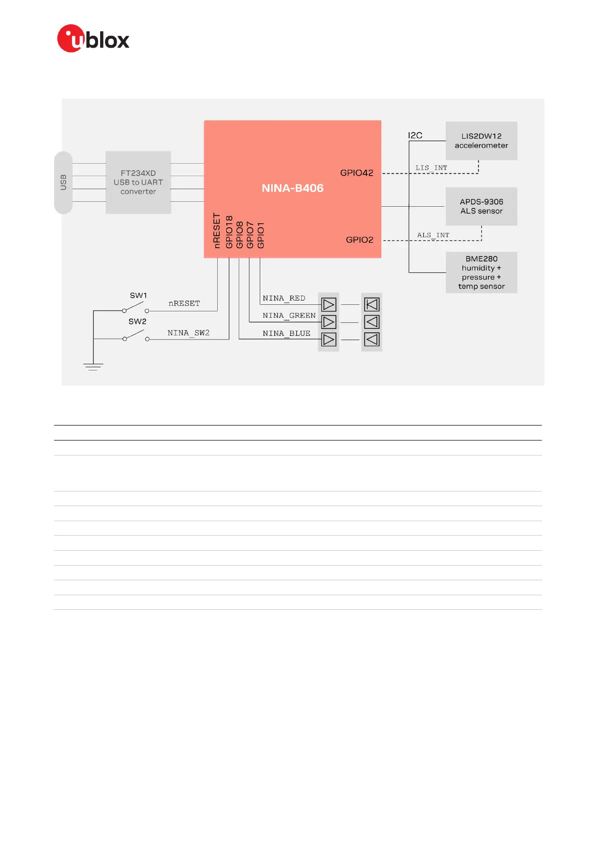
The main components of any C209 tag are shown in Figure 23.
Figure 23: C209 main functional components
The important pin definitions on the C209 application board are described in Table 6.
Interrupt signal from Ambient Light
Sensor
May cause current leak in default configuration.
See C209 GitHub repository [12] for more
information.
GREEN system status signal
BLUE system status signal
UART request to send control signal
Used only when hardware flow control is enabled
UART clear to send control signal
Used only when hardware flow control is enabled
Interrupt signal from accelerometer
Table 6: Important pin definitions on the C209
For more information about programming the module, see also the NINA-B4 system integration
manual [13] and NINA-B40 data sheet [14]. See also C209 schematics.
☞ Although the sensors on the C209 application board are not used in the latest direction-finding
tag software from u-blox, the sensors can be utilized in any customer application.
 Loading...