• Install a shut-off valve in the 1/4 inch supply line.
• Connect sufficient tubing to
the unit to allow the unit to be
moved for cleaning and ser-
vicing. However, make cer-
tain that the tubing is not
pinched or damaged during
installation.
• U-Line specifies the use of
copper tubing for installation.
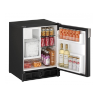
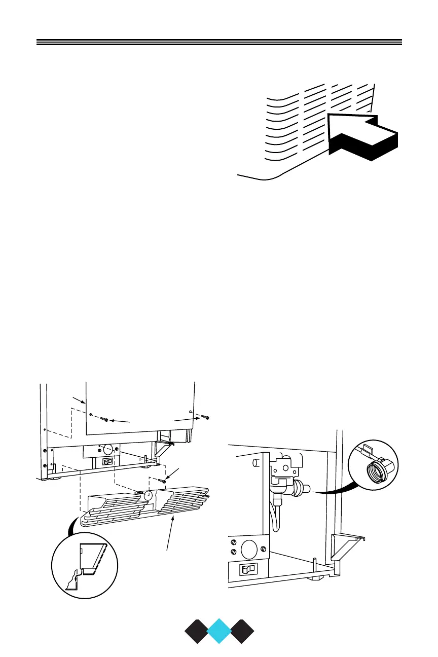
Position the unit to allow free
air flow through the front grille
(see Figure 3).
7. Wipe the inside and outside of the unit with a damp cloth.
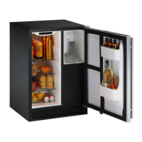
CONNECTING THE WATER SUPPLY
10
User’s Manual
Figure 4
Figure 5
1. Remove access panel from
front of the unit (see Figure
4).
2. Remove the back panel to
ease water line connection.
3. Install the 1/4 inch copper
water line, from the main
water source. The water
line is inserted through the
hole in the rear of the unit,
through a clip on the sidewall
to connect to the solenoid
valve in the front (see Figure
5).
 Loading...