EasyManuals Logo

U-Line ICE-MAKER User Manual

U-Line ICE-MAKER
56 pages
To Next Page IconTo Next Page
To Previous Page IconTo Previous Page
Page #30 background imageLoading...
Page #30 background image
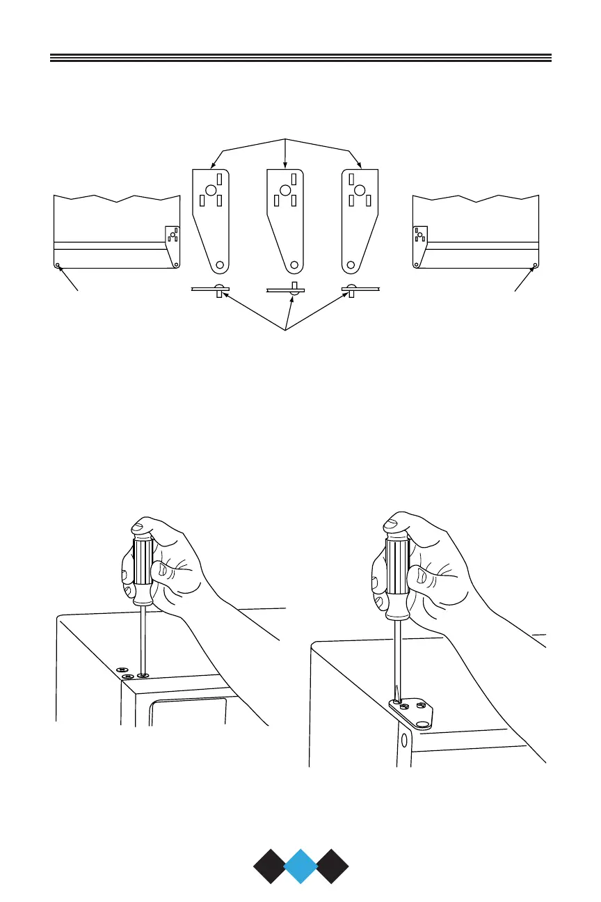
8. Remove pivot screw from top hinge, invert screw and reinstall
pivot screw in top hinge (Figure 28).
Figure 28
HINGE
RIGHT SIDE
DOOR SWING
LEFT SIDE
DOOR SWING
RIGHT SIDE
HINGE
INVERT
SCREW
INVERT
HINGE
SCREW
UL115
PLASTIC
PLUG
HOLE
PLASTIC
PLUG
HOLE
28
User’s Manual
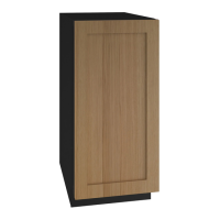
9. Remove three plastic screw
plugs in hinge holes, top of
cabinet, opposite side. Be
careful not to scratch cabinet
(Figure 29).
Figure 29
10. Place door on lower hinge pin.
Invert and install upper hinge
on door.
UL114A
11. Fasten upper hinge to unit
(three screws). Partially tight-
en screws until door is aligned
(Figure 30).
Figure 30
UL119
30035 User Manual Body.qxd 1/5/05 8:08 AM Page 28

Questions and Answers:

Question and Answer IconNeed help?

Do you have a question about the U-Line ICE-MAKER and is the answer not in the manual?

U-Line ICE-MAKER Specifications

General IconGeneral
Ice ShapeCrescent
Power SourceElectric
Voltage115 V
Installation TypeFreestanding or Built-In
FinishStainless steel
Control TypeDigital
Water SupplyDirect Water Line Connection
MaterialStainless Steel
Warranty1 year parts and labor

Related product manuals