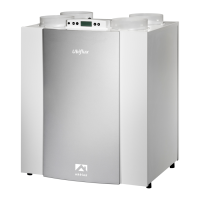
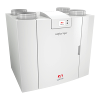
1 = Ubiflux Vigor W325 right-hand version (place level)
2 = Preferred ventilation air supply
3 = Sewer release
4 = Preferred location of ventilation air discharge; Use insulated ventilation roof sleeve
5 = Thermally insulated piping
6 = Condensate discharge
7 = Sound absorber(s)
8 = Duct to and from house
6 = Condensater discharge
7 = Sound absorber(s)
8 = Duct to and from house
5.5 Electrical connections
5.5.1 Connecting the power plug
The appliance can be connected to an easily accessible, earthed wall socket
with the plug that is mounted to the appliance. The electric installation must
comply with the requirements of your power company.
5.5.2 Connecting the multiple switch
The multiple switch (not supplied with the appliance) is connected to the modular connector type RJ12
(connector X14) that is placed on the rear of the display cap of the appliance (® Exploded view of appliance page
10). For connection examples of multiple switch (® Connecting position switch page 37). A wireless remote
control (® Connecting wireless remote control (without filter indication) page 39) and a combination of multiple
switches is also possible (® Connecting extra multiple switch with filter indication page 40).
The 4-way switch can also be used to activate a 30-minutes boost mode by putting the switch to setting 3 for less
than 2 seconds and directly turning it back to setting 1 or 2. The boost mode can be reset by putting the switch to
setting 3 for longerthan 2 seconds or by switching it to absence mode ( ).
Ubiflux Vigor W325 615743-G
 Loading...