SARA-G450 - System integration manual
UBX-18046432 - R08 System description Page 38 of 143
C1-Public
The UART is disabled as long as the RTS line is held to OFF, but the UART is enabled in the following
cases:
If the module needs to transmit some data over the UART (e.g. URC)
During a PSD data call with external context activation
During a voice call
If a data is sent by the DTE, it causes the system wake-up due to the “wake-up via data reception”
feature described in the following subsection, and the UART will be then kept enabled after the
last data received according to the timeout previously set with the AT+UPSV=1 configuration
When an OFF-to-ON transition occurs on the RTS input line, the UART is re-enabled and the module,
if it was in idle mode, switches from idle to active mode after ~20 ms: this is the UART and module
“wake-up time”.
If the RTS line is set to ON by the DTE, then the module is not allowed to enter the low power idle mode
and the UART is kept enabled.
Wake-up via data reception
The UART wake-up via data reception consists of a special configuration of the module TXD input line
that causes the system wake-up when a high-to-low (OFF-to-ON) transition occurs on the TXD input
line. In particular, the UART is enabled and the module switches from the low power idle mode to active
mode within ~20 ms from the first character received: this is the system “wake-up time”.
As a consequence, the first character sent by the DTE when the UART is disabled (i.e. the wake-up
character) is not a valid communication character even if the wake-up via data reception configuration
is active, because it cannot be recognized, and the recognition of the subsequent characters is
guaranteed only after the complete system wake-up (i.e. after ~20 ms).
The UART wake-up via data reception configuration is active in the following cases:
AT+UPSV=1 is set with HW flow control both enabled or disabled
AT+UPSV=2 is set with HW flow control disabled, and the RTS line is set OFF
Figure 18 and Figure 19 show examples of common scenarios and timing constraints:
AT+UPSV=1 power saving configuration is active and the timeout from last data received to idle
mode start is set to 2000 frames (AT+UPSV=1,2000)
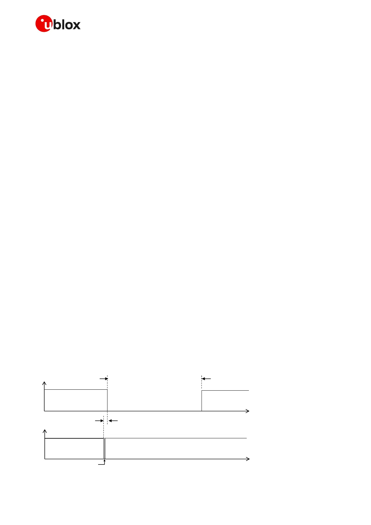
Figure 18 shows the case where the module UART is disabled and only a wake-up is forced. In this
scenario the only character sent by the DTE is the wake-up character; as a consequence, the DCE
module UART is disabled when the timeout from last data received expires (2000 frames without data
reception, as the default case).
OFF
ON
DCE UART is enabled for 2000 GSM frames (~9.2 s)
time
Wake up time: ~20 ms
time
TXD input
Wake up character
Not recognized by DCE
UART
OFF
ON
Figure 18: Wake-up via data reception without further communication

 Loading...