SARA-G450 - System integration manual
UBX-18046432 - R08 System description Page 39 of 143
C1-Public
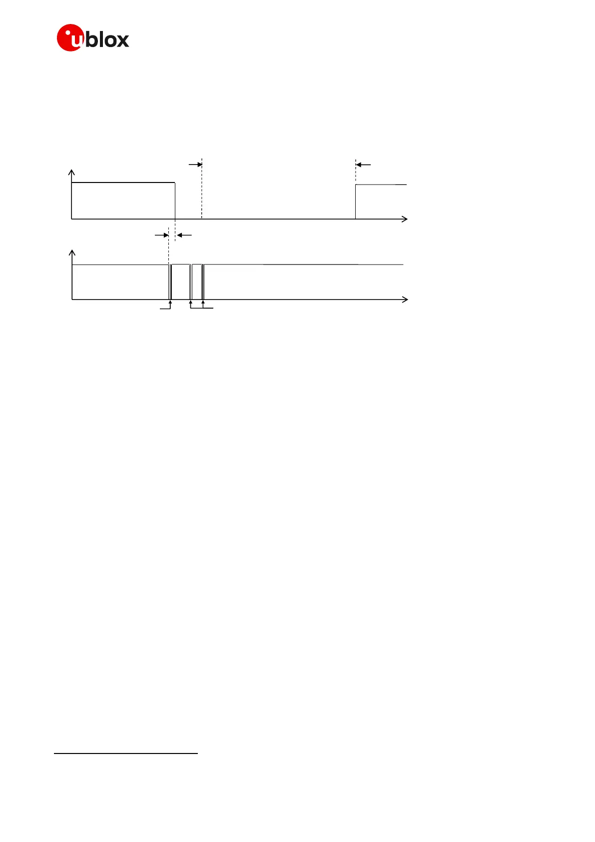
Figure 19 shows the case where in addition to the wake-up character further (valid) characters are
sent. The wake-up character wakes up the module UART. The other characters must be sent after
the “wake-up time” of ~20 ms. If this condition is satisfied, the module (DCE) recognizes characters.
The module will disable the UART after 2000 GSM frames from the latest data reception.
DCE UART is enabled for 2000 GSM frames (~9.2s)
after the last data received
time
Wake up time: ~20 ms
time
Wake up character
Not recognized by DCE
Valid characters
Recognized by DCE
OFF
ON
TXD input
UART
OFF
ON
Figure 19: Wake-up via data reception with further communication
☞ The “wake-up via data reception” feature cannot be disabled.
☞ The UART autobauding does not work when “wake-up via data reception” feature is enabled; if
AT+IPR=0 is set, when issuing AT+UPSV=1 or AT+UPSV=2 the module starts working at a fixed
baud rate of 115200 bit/s, regardless of the baud rate previously recognized. So, if the desired baud
rate is different from 115200 bit/s, it is needed to be set with +IPR AT command before setting
+UPSV (see u-blox AT commands manual [11]).
☞ It is recommended to avoid having power saving enabled when the UART interface is in data mode,
otherwise some data loss may occur.
1.9.1.5 Multiplexer protocol (3GPP TS 27.010)
SARA-G450 modules have a software layer with MUX functionality, the 3GPP TS 27.010 multiplexer
protocol [20], available on the UART physical link. The auxiliary UART and the DDC (I2C) serial
interfaces do not support the multiplexer protocol.
This is a data link protocol (layer 2 of the OSI model) which uses HDLC-like framing and operates
between the module (DCE) and the application processor (DTE), and allows a number of simultaneous
sessions over the used physical link (UART): the user can concurrently use AT command interface on
one MUX channel and data communication on another MUX channel.
The following virtual channels are defined:
Channel 0: control channel
Channel 1-5: AT and data
Channel 6: GNSS tunneling
Not supported by the “00” product version

 Loading...