SARA-G450 - System integration manual
UBX-18046432 - R08 Design-in Page 65 of 143
C1-Public
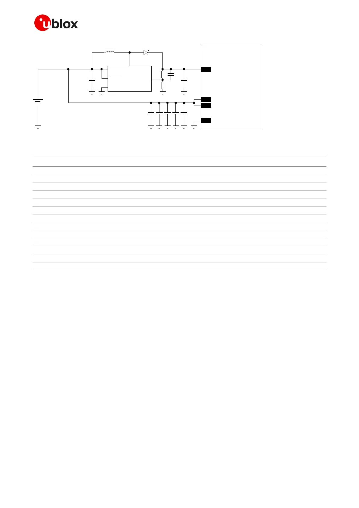
C1 C4
GND
C3C2 C5
SARA-G450
52
VCC
53
VCC
51
VCC
+
Li-Ion/Li-Pol
battery
C6
SWVIN
SHDN
GND
FB
C7
R1
R2
L1
U1
Step-up
regulator
D1
C8
Figure 28: VCC circuit example with separate supply
Part number - Manufacturer
330 µF capacitor tantalum D_SIZE 6.3 V 45 m
T520D337M006ATE045 - KEMET
100 nF capacitor ceramic X7R 0402 10% 16 V
GRM155R61A104KA01 - Murata
10 nF capacitor ceramic X7R 0402 10% 16 V
GRM155R71C103KA01 - Murata
56 pF capacitor ceramic C0G 0402 5% 25 V
GRM1555C1E560JA01 - Murata
15 pF capacitor ceramic C0G 0402 5% 25 V
GRM1555C1E150JA01 - Murata
10 µF capacitor ceramic X5R 0603 20% 6.3 V
GRM188R60J106ME47 - Murata
22 µF capacitor ceramic X5R 1210 10% 25 V
GRM32ER61E226KE15 - Murata
10 pF capacitor ceramic C0G 0402 5% 25 V
GRM1555C1E100JA01 - Murata
SS14 - Vishay General Semiconductor
10 µH inductor 20% 1 A 276 m
SRN3015-100M - Bourns Inc.
1 M resistor 0402 5% 0.063 W
RC0402FR-071ML - Yageo Phycomp
412 k resistor 0402 5% 0.063 W
RC0402FR-07412KL - Yageo Phycomp
AP3015 - Diodes Incorporated
Table 18: Examples of components for the VCC circuit with separate supply
2.2.1.8 Guidelines for external battery charging circuit
Application devices powered by a Li-Ion (or Li-Polymer) battery pack should implement a suitable
battery charger design considering SARA-G450 modules do not have an on-board charging circuit.
In the application circuit described in Figure 29 and Table 19, a rechargeable Li-Ion (or Li-Polymer)
battery pack, which features suitable pulse and DC discharge current capabilities and low DC series
resistance, is directly connected to the VCC supply input of the module. Battery charging is fully
managed by the STMicroelectronics L6924U battery charger IC that, from a USB source (5.0 V
typical), charges the battery as a linear charger, in three phases:
Pre-charge constant current (active when the battery is deeply discharged): the battery is
charged with a low current, set to 10% of the fast-charge current.
Fast-charge constant current: the battery is charged with the maximum current, configured by
the value of an external resistor to a value suitable for USB power source (~500 mA).
Constant voltage: when the battery voltage reaches the regulated output voltage (4.2 V), the
L6924U starts to reduce the current until the charge termination is done. The charging progress
ends when the charging current reaches the value configured by an external resistor to ~15 mA or
when the charging timer reaches the value configured by an external capacitor to ~9800 s.
Using a battery pack with an internal NTC resistor, the L6924U can monitor the battery temperature
to protect the battery from operating under unsafe thermal conditions.

 Loading...