SARA-G450 - System integration manual
UBX-18046432 - R08 Design-in Page 66 of 143
C1-Public
The L6924U, as linear charger, is more suitable for applications where the charging source has a
relatively low nominal voltage (~5 V), so that a switching charger is suggested for applications where
the charging source has a relatively high nominal voltage (e.g. ~12 V, refer to the following section
2.2.1.9 for specific design-in), even if the L6924U can also charge from an AC wall adapter as its input
voltage range is tolerant up to 12 V: when a current-limited adapter is used, it can operate in
quasi-pulse mode, thereby reducing power dissipation.
C5 C8
GND
C7C6 C9
SARA-G450
52
VCC
53
VCC
51
VCC
+
USB
supply
C3
R4
θ
U1
IUSB
IAC
IEND
TPRG
SD
VIN
VINSNS
MODE
ISEL
C2C1
5V
TH
GND
VOUT
VOSNS
VREF
R1
R2
R3
Li-Ion/Li-Pol
battery pack
D1
B1
C4
Li-Ion/Li-Polymer
battery charger IC
D2
Ferrite bead
or 0Ω
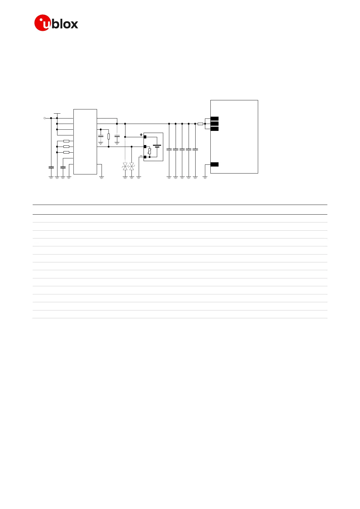
Figure 29: Li-Ion (or Li-Polymer) battery charging application circuit
Part number - Manufacturer
Li-Ion (or Li-Polymer) battery pack with 470 NTC
1 µF capacitor ceramic X7R 0603 10% 16 V
GRM188R71C105KA12 - Murata
10 nF capacitor ceramic X7R 0402 10% 16 V
GRM155R71C103KA01 - Murata
1 nF capacitor ceramic X7R 0402 10% 50 V
GRM155R71H102KA01 - Murata
330 µF capacitor tantalum D_SIZE 6.3 V 45 m
T520D337M006ATE045 - KEMET
100 nF capacitor ceramic X7R 0402 10% 16 V
GRM155R61A104KA01 - Murata
56 pF capacitor ceramic C0G 0402 5% 25 V
GRM1555C1E560JA01 - Murata
15 pF capacitor ceramic C0G 0402 5% 25 V
GRM1555C1E150JA01 - Murata
Low capacitance ESD protection
24 k resistor 0402 5% 0.1 W
RC0402JR-0724KL - Yageo Phycomp
3.3 k resistor 0402 5% 0.1 W
RC0402JR-073K3L - Yageo Phycomp
1.0 k resistor 0402 5% 0.1 W
RC0402JR-071K0L - Yageo Phycomp
Li-Ion (or Li-Polymer) linear battery charger IC
L6924U - STMicroelectronics
Table 19: Suggested components for Li-Ion (or Li-Polymer) battery charging application circuit
2.2.1.9 Guidelines for external charging and power path management circuit
Application devices where both a permanent primary supply / charging source (e.g. ~12 V) and a
rechargeable back-up battery (e.g. 3.7 V Li-Pol) are available at the same time as possible supply
source should implement a suitable charger / regulator with integrated power path management
function to supply the module and the whole device while simultaneously and independently charging
the battery.
Figure 30 illustrates a simplified block diagram circuit showing the working principle of a
charger / regulator with integrated power path management function. This component allows the
system to be powered by a permanent primary supply source (e.g. ~12 V) using the integrated
regulator which simultaneously and independently recharges the battery (e.g. 3.7 V Li-Pol) that
represents the back-up supply source of the system: the power path management feature permits
the battery to supplement the system current requirements when the primary supply source is not
available or cannot deliver the peak system currents.

 Loading...