ZED-F9R-Integration manual
Casting
If casting is required, use viscose or another type of silicon pottant. The OEM is strongly advised to
qualify such processes in combination with the module before implementing this in the production.
Casting will void the warranty.
Grounding metal covers
Attempts to improve grounding by soldering ground cables, wick or other forms of metal strips
directly onto the EMI covers is done at the customer’s own risk. The numerous ground pins should
be sufficient to provide optimum immunity to interferences and noise.
u-blox makes no warranty for damages to the module caused by soldering metal cables or
any other forms of metal strips directly onto the EMI covers.
Use of ultrasonic processes
Some components on the module are sensitive to ultrasonic waves. Use of any ultrasonic processes
(cleaning, welding etc.) may cause damage to the GNSS receiver.
u-blox offers no warranty against damages to the module caused by ultrasonic processes.
5.3 Tapes
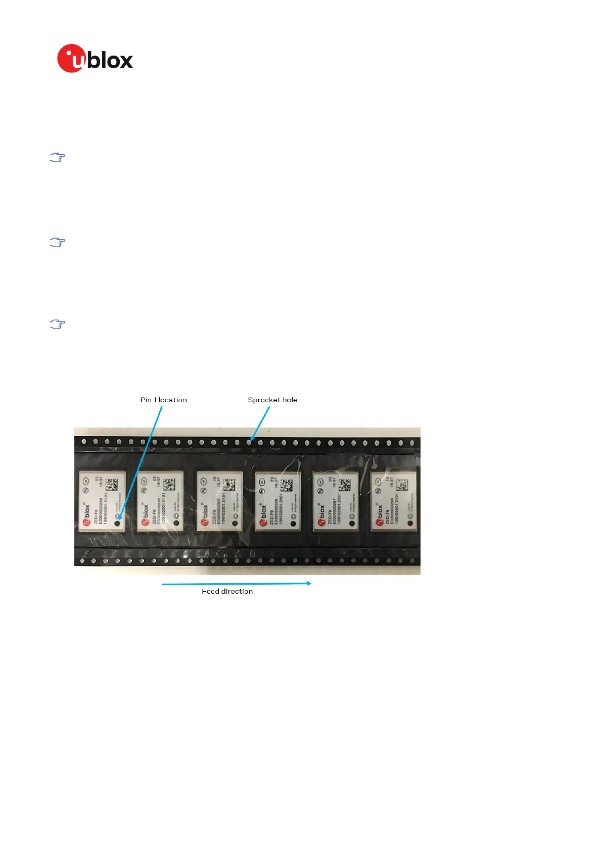
Figure 51 shows the feed direction and illustrates the orientation of the ZED-F9Rs on the tape:
Figure 51: Orientation of ZED-F9R on the tape
The feed direction to the pick and place pick-up is shown by the orientation of the pin 1 location. In
Figure 51, with pin 1 location on the bottom of the tape, the feed direction into the pick and place
pick-up is from the reel (located on the right of the figure) towards left.
The dimensions of the tapes for ZED-F9R are specified in Figure 52 (measurements in mm).
UBX-20039643 - R06
5 Product handling Page 108 of 119
C1-Public
 Loading...