ZED-F9R-Integration manual
message providing more details. When the vehicle is subject to sufficient dynamics (i.e. left and
right turns during a normal drive), the automatic IMU-mount alignment engine will estimate the
IMU-mount misalignment angles. Once the automatic IMU-mount alignment engine has sufficient
confidence in the estimated angles, the IMU-mount misalignment angles initialization phase is
completed. The raw accelerometer and gyroscope data (that is, the IMU observations) are then
compensated for IMU-mount misalignment and sensor fusion can begin. The resulting IMU-mount
misalignment angles are output in the UBX-ESF-ALG message.
Enabling/disabling automatic IMU-mount alignment
The user can activate/deactivate the automatic IMU-mount alignment with the CFG-SFIMU-
AUTO_MNTALG_ENA configuration key.
If automatic IMU-mount alignment is deactivated while aligning, the estimated
misalignment angles that were available at deactivation time are used (only if they were
initialized, see the next section). If automatic IMU-mount alignment is reactivated,
alignment is pursued by starting from the state where deactivation happened.
3.2.4.1.2 User-defined IMU-mount alignment
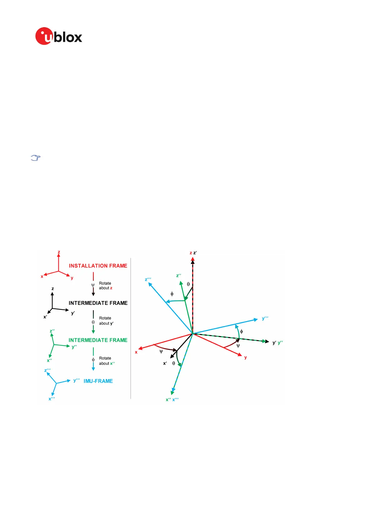
It is possible to configure the IMU-mount misalignment angles using the CFG-SFIMU-IMU_MNTALG
configuration keys. The values that should be set in the configuration message are the Euler angles
required to rotate the installation frame to the IMU-frame. The IMU-mount yaw rotation should be
performed first, then the IMU-mount pitch and finally the IMU-mount roll. At each stage, the rotation
is around the appropriate axis of the transformed installation frame, meaning that the order of the
rotation sequence is important (see the figure below).
Figure 2: Euler angles
If there is only a single IMU-mount misalignment angle, it may be measured as shown in the three
examples below.
UBX-20039643 - R06
3 Receiver functionality Page 24 of 119
C1-Public
 Loading...