EasyManuals Logo

UNI-T UT207 User Manual

UNI-T UT207
54 pages
To Next Page IconTo Next Page
To Previous Page IconTo Previous Page
Page #25 background imageLoading...
Page #25 background image
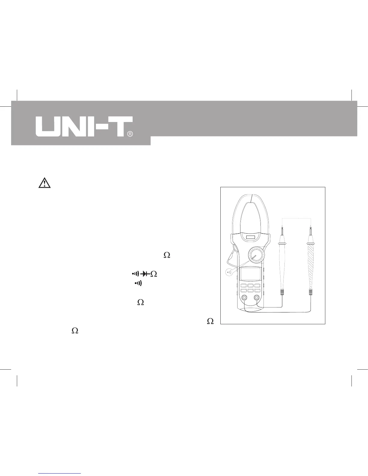
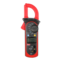
D. Testing for Continuity (see figure 6)
To avoid damages to the Meter or to the devices
under test, disconnect circuit power and
discharge all the high-voltage capacitors before
measuring continuity.
To test for continuity, connect the Meter as follows:
Insert the red test lead into the V Hz terminal
and the black test lead into the COM terminal.
Set the rotary switch to and press
SELECT button to select measurement mode.
The buzzer sounds if the resistance of a circuit
under test is less than 30 .
The buzzer may or may not sound if the
resistance of a circuit under test is between 30
to 100 .
The buzzer does not sound if the resistance of
1.
2.
3.
4.
5.
Red Black
Warning
Figure 6
Model UT207/208: OPERATING MANUAL
24

Questions and Answers:

Question and Answer IconNeed help?

Do you have a question about the UNI-T UT207 and is the answer not in the manual?

UNI-T UT207 Specifications

General IconGeneral
BacklightYes
AC current range66 - 1000 A
DC voltage range6.6 - 600 V
Resistance range20 - 20000 Ω
Basic accuracy (frequency)±(0.1%+3)
Basic accuracy (DC current)±(1.5%+8)
Basic accuracy (DC voltage)±(0.8%+1)
Basic accuracy (resistance)±(1%+2)
Temperature measurement range-40 - 1000 °C
Dimensions (WxDxH)105 x 45 x 286 mm
Battery voltage9 V
Weight and Dimensions IconWeight and Dimensions
Weight533 g

Related product manuals