Installation and Configuration
Supply Voltage
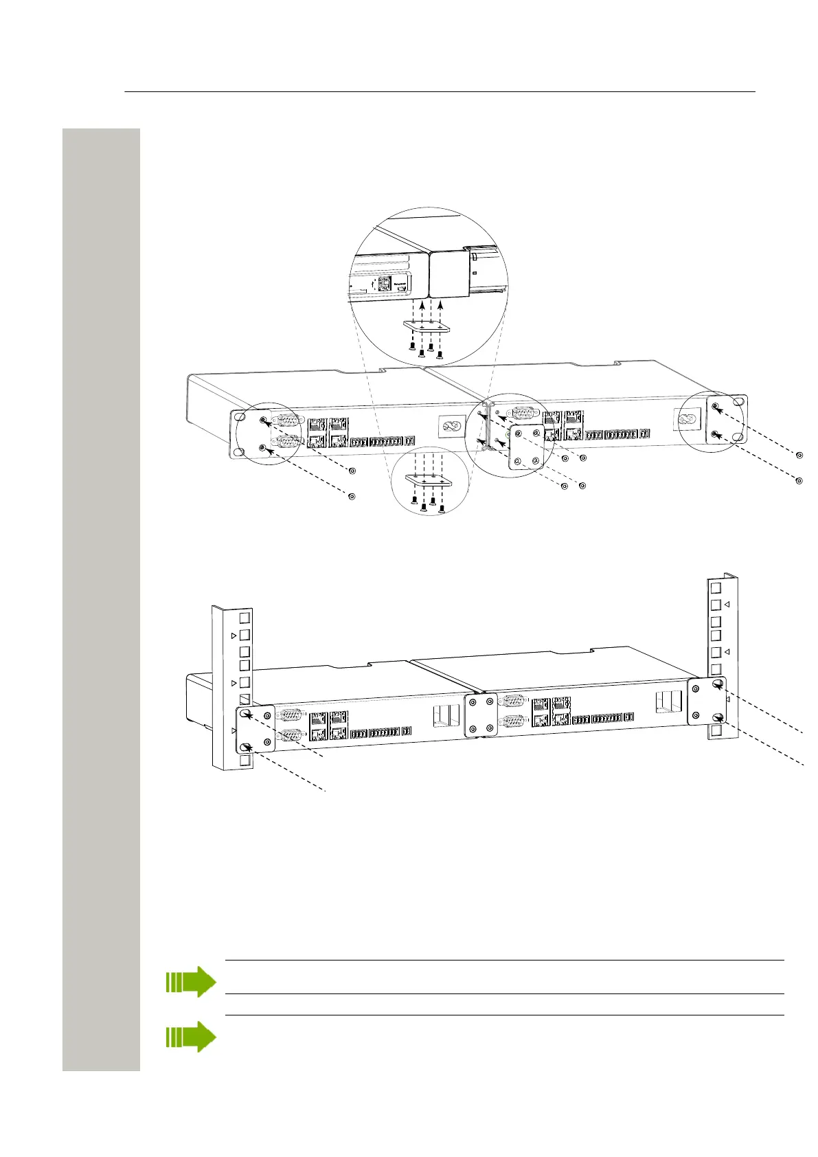
1) Use the supplied assembly brackets and mount the two modules together, both on the rear
side and on the bottom side, see figure below.
2) Use the two small reverse assembly brackets and fasten one on the right rear side and the
other on the left rear side.
Figure 12: Rear mounted double in rack
3) Fasten the assembly brackets in the rack, see below (screws not included).
Figure 13: Rear mounted double in rack
Supply Voltage
Wireless Service Gateway WSG can be connected to an external power supply (12-24 V DC bat-
tery or power source) as a complement to the primary power supply (100-240 V AC). If the pri-
mary power supply fails it switches over to the external power supply automatically, without any
negative influence on the running application.
24 hours backup requires a 12V battery with at least 4.8 Ah.
For installation on ships the 12 - 24 V DC input should be used to meet the regulatory re-
quirements for safety and EMC. (To meet the regulatory requirements for EMC alone, the
A31003-M2000-J109-01-7631, 30/06/2020
Wireless Service Gateway WSG, Installation Guide 19
 Loading...