Installation and Configuration
Accessing Wireless Service Gateway WSG
When the Wireless Service Gateway WSG is running the relay is closed, i.e. the error relay out-
put is activated when the relay releases, for example if the power is dropped. At power up or
restart the relay is released until the applications are working properly. If the relay is released
longer the Wireless Service Gateway WSG is malfunctioning.
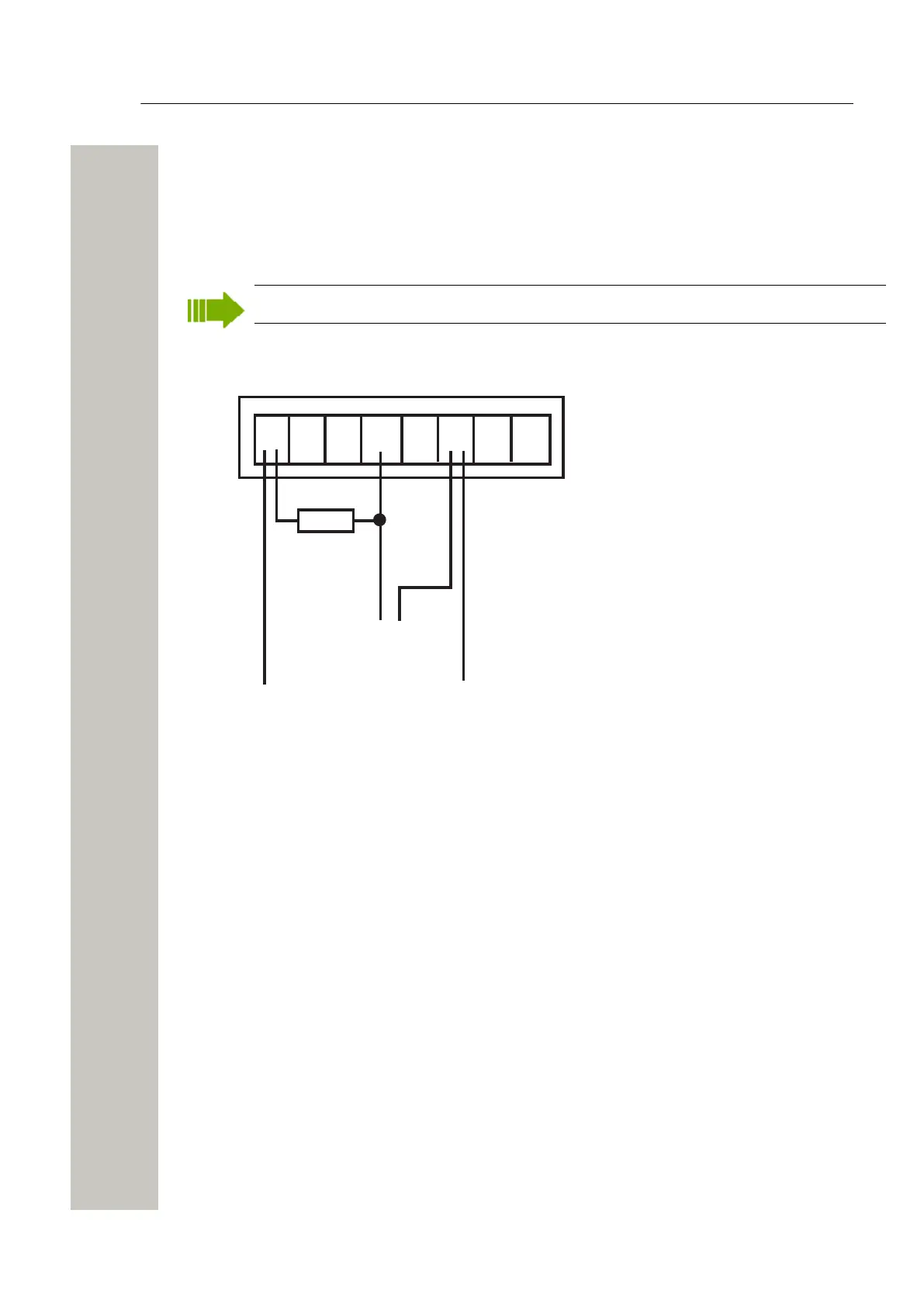
Connection of AUX Inputs and AUX Outputs
The application of the inputs and outputs are software dependent
+V In In Out Out GND
Ext 1 2 1 2 Ext
External
equipment
Error
1 2
A
+12 V DC GND
Pull-up
resistor
Figure 18: AUX inputs and outputs
Two digital inputs and two digital outputs can be connected. The outputs are of open-collector
type and the output signals are dimensioned for 100 mA at max 12 V. A pull-up resistor should
be connected to the output as shown in Figure 18 on page 22.
Galvanic isolation of the inputs and outputs is provided by using a separate power supply.
If galvanic isolation is not needed and Wireless Service Gateway WSG is supplied by an exter-
nal 12 V power source, the supply voltage can be taken from the 12-24 V DC screw connector
by connecting +V Ext to “+” and GND Ext to “-”.
The inputs In 1 and In 2 are active when they are connected to 12 V. When the output Out 1 is
active, the potential in point A in Figure 18 on page 22 will be close to 0 V. The same applies
for a similar connection for Out 2.
Accessing Wireless Service Gateway WSG
The Wireless Service Gateway WSG can be accessed either via an IP network or directly via the
management port (mini-USB). The web browser Internet Explorer 8.0™ or later is used for ac-
cessing the product´s web interface.
Access via the Network
It is recommended that this module always gets the same IP address if it communicates with oth-
er equipment, to prevent it from losing contact with the equipment after a restart. Inform the net-
A31003-M2000-J109-01-7631, 30/06/2020
22 Wireless Service Gateway WSG, Installation Guide
 Loading...