Installation and Configuration
Connections
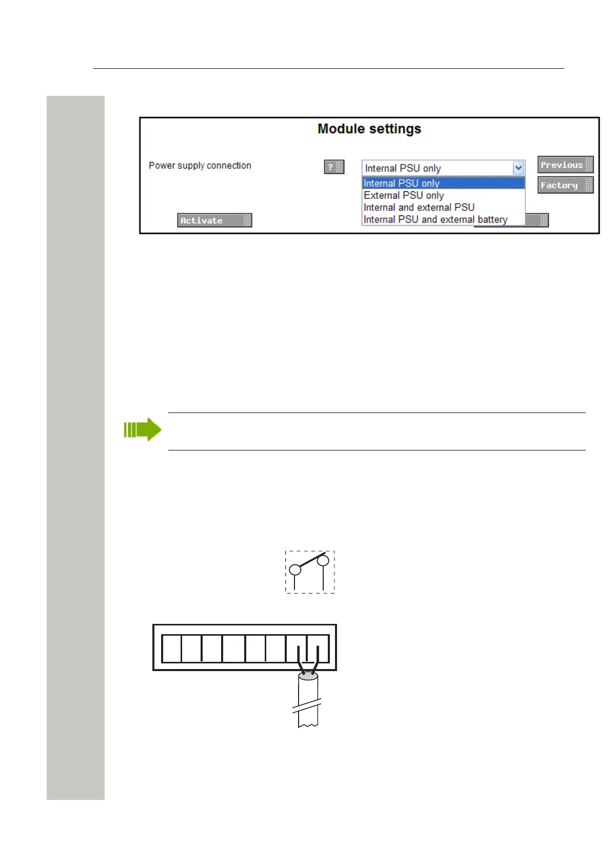
2) Select Power supply in the menu on the Advanced Configuration page.
Figure 16: Power supply parameter
3) Select setting in the drop-down list (Internal PSU only, External PSU only, Internal and exter-
nal PSU or Internal PSU and external battery).
4) Click “Activate”.
Connections
Ethernet Ports
The Wireless Service Gateway WSG has two 10baseT/100baseT Ethernet modular jacks (RJ45)
but only the jack marked 1 is currently in use (the jack marked 2 is intended for future releases).
Shielded ethernet cables should be used for installation on trains to meet the regulatory re-
quirements for railway equipment.
Error Relay Output
A relay output is used to indicate Wireless Service Gateway WSG module malfunction and can
also be used to indicate other errors. See the application documentation for more information
about functionality. Connections are made with twisted pairs to 1 and 2 on screw connector Er-
ror.
+V In In Out Out GND
Ext 1 2 1 2 Ext
Error
1 2
Error rela
Figure 17: Error relay
A31003-M2000-J109-01-7631, 30/06/2020
Wireless Service Gateway WSG, Installation Guide 21
 Loading...