14
Modbus interface
The tables that follow in this chapter specify the addresses of the readable and writable words that the customer is able to access. The
customer may read and/or write the values using SCADA programs, PLCs, or similar.
The entries under Access have the following meanings:
R/O Read Only, value can only be read
R/W Read/Write, value can be read and written
The number of characters specified under Data type in the case of character strings includes the final \0.
Char10 means that the text is up to 9 characters long. The final \0 character is then added to this
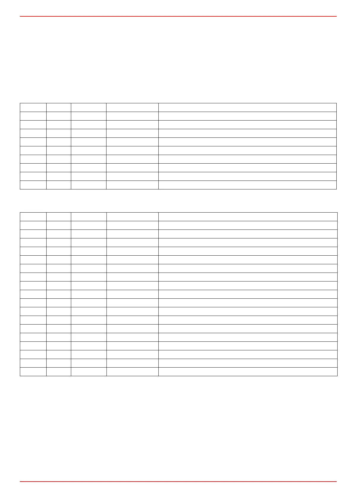
User level
Parameter level
Address Access Data type Signal reference Parameter
0x0000 R/O Float X1 Analog input InP1
0x0002 R/O Float X2 Analog input InP2
0x0004 R/O Float X3 Analog input InP2
0x0006 R/O Float WR Actual setpoint
0x0008 R/W Float SP1 Setpoint 1
0x000A R/W Float SP2 (= dSP) Setpoint 2
0x1035 R/O Float --- Analog input InP3 (unfiltered)
0x1043 R/O Float --- Actual angular positioning
0x1058 R/O Word B1 Burner alarm
Address Access Data type Signal reference Parameter
0x3000 R/W Float Pb1 Proportional range 1
0x3004 R/W Float dt Derivative action time
0x3006 R/W Float rt Integral action time
0x300C R/W Float db Dead band
0x3012 R/W Word tt Controlling element running time
0x3016 R/W Float HYS1 Switch-on threshold
0x3018 R/W Float HYS2 Switch-off threshold down
0x301A R/W Float HYS3 Switch-off threshold up
0x301C R/W Float HYS4 Switch-on threshold (cooling)
0x301E R/W Float HYS5 Switch-off threshold down (cooling)
0x3020 R/W Float HYS6 Switch-off threshold up (cooling)
0x3022 R/W Float q Reaction threshold
0x3080 R/W Float At1 Outside temperature 1
0x3082 R/W Float Ht2 Boiler temperature 1
0x3084 R/W Float At2 Outside temperature 2
0x3086 R/W Float Ht2 Boiler temperature 2