24V
EI1
24V
SI0
24V
SI1
24V
EI0
Safety
Safeguard Stop
Emergency Stop
24V 0V
24V
0V
24V
CI1
24V
CI2
24V
CI3
24V
CI0
Configurable Inputs
24V
CI5
24V
CI6
24V
CI7
24V
CI4
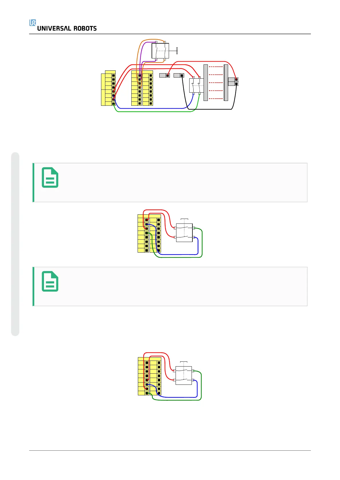
Three-Position Enabling Device
The illustration below shows how to connect a Three-Position Enabling Device. See sectionThree-
Position Enabling Device for more about Three-Position Enabling Device.
NOTE
The Universal Robots safety system does not support multiple external Three-
Position Enabling Devices.
24V
CI1
24V
CI2
24V
CI3
24V
CI0
24V
CI5
24V
CI6
24V
CI7
24V
CI4
Configurable Inputs
3-Position Switch
NOTE
The two input channels for the Three-Position Enabling Device input have a
disagreement tolerance of 1 second.
Operational Mode Switch
The illustration below shows an Operational Mode Switch. See sectionOperational Modes for more
about operational Modes.
24V
CI1
24V
CI2
24V
CI3
24V
CI0
24V
CI5
24V
CI6
24V
CI7
24V
CI4
Configurable Inputs
Operational mode Switch
UR5e 38 Hardware Manual
4.Electrical Interface
Copyright © 2009–2022 by UniversalRobotsA/S. All rights reserved.
 Loading...


