CAUTION
1. Analog Inputs are not protected against overvoltage in current mode.
Exceeding the limit in the electrical specification can cause permanent
damage to the input.
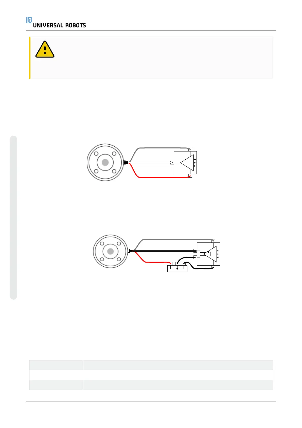
Using Tool Analog Inputs, Nondifferential
This example shows an analog sensor connection with a nondifferential output. The sensor output
can be either current or voltage, as long as the input mode of that Analog Input is set to the same
on the I/O tab.
Note: You can check that a sensor with voltage output can drive the internal resistance of the tool,
or the measurement might be invalid.
Using Tool Analog Inputs, Differential
This example shows an analog sensor connection with a differential output. Connecting the
negative output part to GND (0V), works in the same way as a nondifferential sensor.
4.8.7. Tool Communication I/O
•
Signal requests The RS485 signals use internal fail-safe biasing. If the attached device does
not support this fail-safe, signal biasing must either be done in the attached tool, or added
externally by adding pull-up resistors to RS485+ and pull-down to RS485-.
•
Latency The latency of messages sent via the tool connector ranges from 2ms to 4ms, from
the time the message is written on the PC to the start of the message on the RS485. A buffer
stores data sent to the tool connector until the line goes idle. Once 1000 bytes of data have
been received, the message is written on the device.
Baud Rates 9.6k, 19.2k, 38.4k, 57.6k, 115.2k, 1M, 2M, 5M
Stop Bits 1, 2
Parity None, Odd, Even
UR5e 50 Hardware Manual
4.Electrical Interface
Copyright © 2009–2022 by UniversalRobotsA/S. All rights reserved.
 Loading...


