Tool flange The tool output flange (ISO 9409-1) is where the tool is mounted at the tip of the robot. It
is recommended to use a radially slotted hole for the positioning pin to avoid over-
constraining, while keeping precise position.
CAUTION
Very long M8 bolts can press against the bottom of the tool flange and
short circuit the robot.
•
Do not use bolts that extend beyond 10mm to mount the tool.
WARNING
Failure to tighten bolts properly cause injury due to loss of the adapter
flange and/or end effector.
•
Ensure the tool is properly and securely bolted in place.
•
Ensure the tool is constructed such that it cannot create a
hazardous situation by dropping a part unexpectedly.
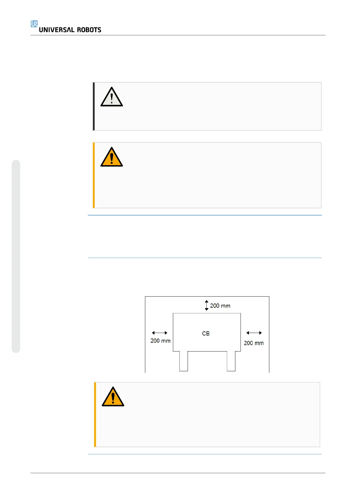
3.5. Control Box Clearance
Description The flow of hot air in the Control Box can result in equipment malfunction.
The Control Box requires a minimum clearance of 50mm on each side for sufficient
cool airflow. The recommended Control Box clearance is 200mm.
WARNING
A wet Control Box can cause fatal injury.
•
Make sure the Control Box and cables do not come into
contact with liquids.
•
Place the Control Box (IP44) in an environment suited for the
IP rating.
UR10e 42 User Manual
3.Mechanical Interface
Copyright © 2009–2024 by UniversalRobotsA/S. All rights reserved.
 Loading...


