Ignition sequence
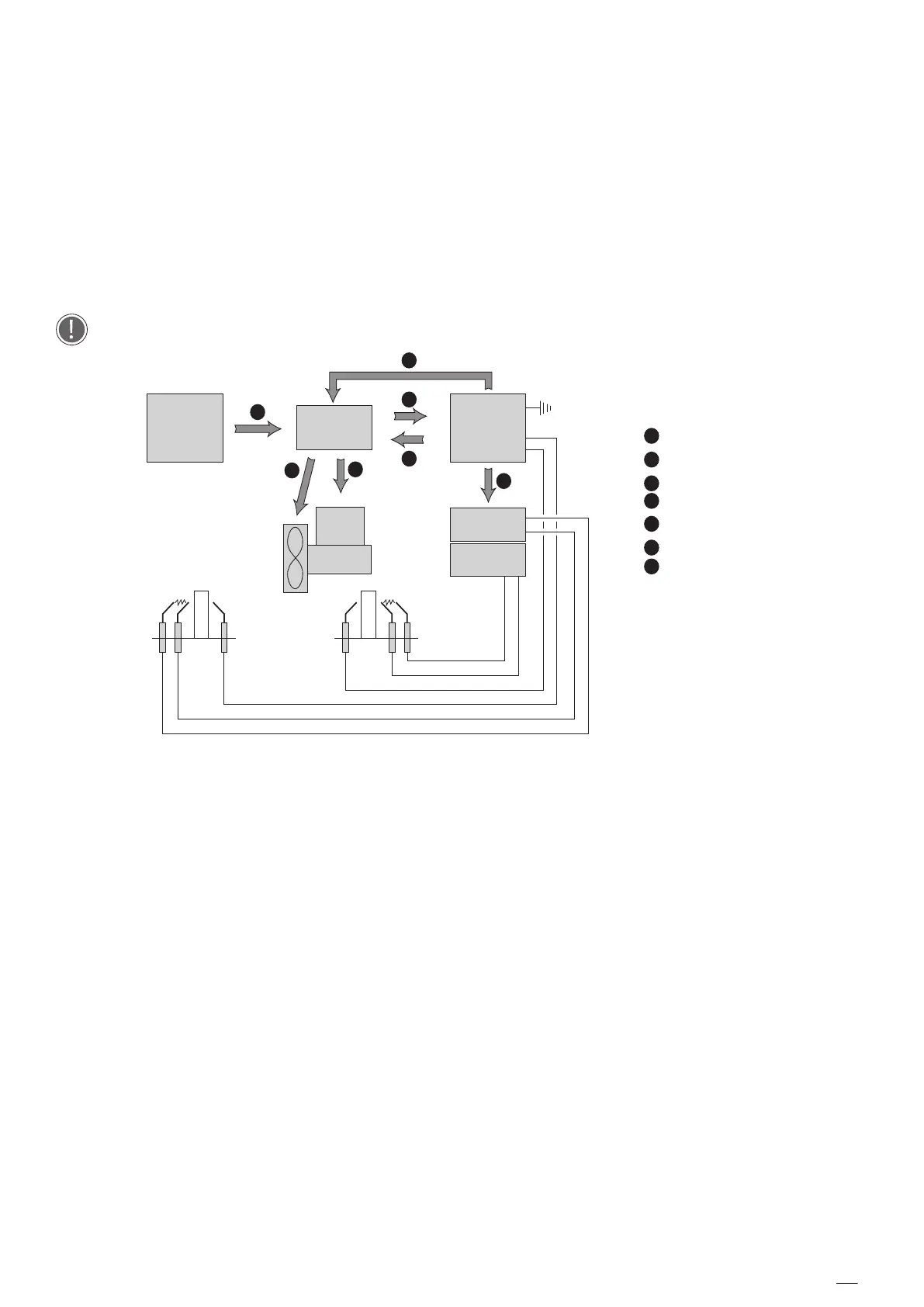
The ignition sequence is described below as shown in :
1. The control board sends the heat demand input to the power board;
2. The power board receives the input and transmits it to the flame control board, through the power
board socket P33;
3. The flame control board activates the blower by using the power board socket P27 or P29;
4. After the startup of the blower, the flame control board produces the ignition sparks by providing 230 V
AC to the ignition electrodes or the contactor, through the flame control board sockets J2 and J4;
5. The flame control board opens the gas valve, sending the input from the J5 flame control board socket
to the P34 power board socket of the power board and then from the P35 or P36 to the gas valve. The
power board supply 230 VAC to the gas valve, the gas valve receives 230 V DC due to a rectifier placed
in the cable harness
There can be a maximum of 3 ignition attempts in total, after that the oven will trigger an AF23 alarm
FLAME
CONTROL
BOARD
CONTROL
BOARD
IGNITER
GAS
VALVE
IGNITER
1
2
6
3
7
4
5
POWER
BOARD
AC-DC
230V AC
3
4
1
HEAT DEMAND
2
START IGNITION CYCLE
BLOWER START-UP
5
SPARK IGNITION
Ignition sequenc e EU system
 Loading...