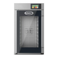
Do you have a question about the Unox MINDMaps CHEFTOP and is the answer not in the manual?
Guidance on navigating and utilizing the manual effectively.
Information for reaching UNOX S.p.A. for support and inquiries.
Explanation of product identification details found on the oven's label.
Feature for cooking multiple products simultaneously for staggered readiness.
Access to curated recipes created by Unox chefs.
Function to optimize tray insertion for simultaneous meal readiness.
Menu for accessing preset programs for quick cooking.
Menu for retrieving HACCP data and controlling consumption.
Detailed list and location of components found on the rear of gas ovens.
Layout and specifications for the PE2037 power board.
Layout and specifications for the PE2038 power board.
Layout and specifications for the PE2143 power board.
Layout and specifications for the PE2102 power board.
Details of the output signals and their functions from the PE2037A board.
Explanation of the symbols and abbreviations used in the input section.
Details and specifications for the bottom temperature probe input.
Information on the door switch 1 input and its function.
Parameters and nominal values for the power supply.
Pin assignment and description for each socket on the power board.
Physical dimensions of the unit.
Operational ranges for temperature and humidity.
Compliance with relevant directives and general regulations.
Details of the output signals and their functions from the PE2038A board.
Details and specifications for various input signals and sensors.
Pin assignment and description for power board sockets.
Physical dimensions of the unit.
Operational ranges for temperature and humidity.
Compliance with relevant directives and general regulations.
Details of the output signals and their functions from the PE2021C board.
Details and specifications for various input signals and sensors.
Parameters and nominal values for the power supply.
Pin assignment and description for power board sockets.
Details of the output signals and their functions from the PE2022A board.
Details and specifications for various input signals and sensors.
Parameters and nominal values for the power supply.
Pin assignment and description for power board sockets.
Physical dimensions of the unit.
Operational ranges for temperature and humidity.
Step-by-step guide for updating the oven software.
Instructions for preparing and using a USB stick for software updates.
Alternative procedure for software upgrade when regular method fails.
Standard procedure for updating oven software via USB.
Steps to load model parameters onto the oven using a USB stick.
Software update steps for ovens without the hyper smoker system.
Visual guide for distinguishing correct and incorrect cables.
Instructions for preparing and using a USB stick for software updates.
Alternative procedure for software upgrade when regular method fails.
Standard procedure for updating oven software via USB.
Steps to load model parameters onto the oven using a USB stick.
Configuration parameters for the oven's core functions.
Settings for connected accessories like probes and smokers.
Functions for installation and software upgrades.
Software update steps for ovens without the hyper smoker system.
Visual guide for distinguishing correct and incorrect cables.
Setting for automatic regulation of cooking parameters for repeatable results.
Menu for humidity and gas fumes calibration.
Overview of steam production cycle and climate conditions.
How the oven operates with humidity measurement set to OFF.
Oven behavior when STEAM.Maxi™ is set to 100%.
How DRY.Maxi™ operates based on set points.
Limits on steam production based on temperature.
How motor speed affects steam production quantity.
Details on the asynchronous single-phase motor used in the ovens.
Explanation of the braking elements used for motor speed control.
How temperature limits fan speed.
Information on motor reversal timing and exceptions.
Conditions under which the motor remains inactive.
Process when ventilation is requested and the system is ready.
Motor behavior after speed stabilization and humidity measurement.
Conditions and process when the oven brakes the motor.
Conditions and process for measuring humidity.
How humidity measurement is performed using motor RPM.
Overview of the ROTOR.Klean system.
Components of the water inlet system after Feb 2020.
Components of the water inlet system before Dec 2016.
Illustration of the detergent tank in different oven models.
Working principle and configuration of self-cleaning solenoid valves.
Washing circuit diagram for European ONE ovens with a single rotor arm.
Washing circuit diagram for US/Japan ONE ovens with a single rotor arm.
Washing circuit diagram for European PLUS ovens with a single rotor arm.
Washing circuit diagram for US/Japan PLUS ovens with a single rotor arm.
Washing circuit diagram for European PLUS ovens with two rotor arms.
Washing circuit diagram for US/Japan PLUS ovens with two rotor arms.
Washing circuit diagram for European PLUS ovens with three rotor arms.
Washing circuit diagram for US/Japan PLUS ovens with three rotor arms.
Visual representation of different rotor arm configurations.
Detailed steps of the long washing program for 2-rotor arm PLUS models.
Options for customizing oven models.
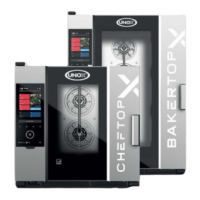
Overview and features of the CHEFTOP MIND.Maps™ ZERO series.
Design and features of cooking chambers A and B.
Information on primary and auxiliary power boards.
Features and specifications of the SPIDO.Gas™ system.
Details on the enhanced motor system for PLUS range ovens.
Components and function of the DRY.Maxi™ system.
Technical details and connection of the PT1000 core probe.
Improvements and features of the cooking chamber temperature probes.
Design and functionality of the new safety thermostat.
Position, function, and activation of the centrifugal fan.
Automatic regulation of cooking parameters for consistent results.
Features for enhanced cooking, including DRY.Plus™ and STEAM.Plus™.
Connectivity and data analysis features for oven usage.
Basic cooking modes and functions.
Features like MIND.Maps™, PROGRAMS, CHEFUNOX, MULTI.Time.
Details on ROTOR.KLEAN™ and integrated cleaning systems.
Material and design of the cooking chamber.
Construction quality and materials used.
Feature allowing door reversal post-installation.
Configuration parameters for the oven's core functions.
Settings for connected accessories like probes and smokers.
Functions for installation and software upgrades.
Table of contents for fault messages.
Procedure to test electrical continuity of cables.
Procedure to test electrical continuity of cables.
Test for back cooling fan power supply.
Check for correct fan airflow direction.
Check power supply to water solenoid.
Check if the water solenoid valve opens.
Test the pressure switch functionality.
Measure probe impedance.
Test ground connection of core probe wires.
Test ground connection of core probe tip.
Check screws on the socket.
Measure voltage applied to the detergent pump.
Check power supply to water solenoid.
Test pressure switch functionality.
Measure power supply to the blower.
Measure blower frequency.
Check power supply to water solenoid.
Test pressure switch functionality.
Check power supply to water solenoid.
Test pressure switch functionality.
Test pressure switch functionality.
Steps to diagnose gas fumes temperature issues.
Measuring electrical continuity of the fumes/power board cable.
Test back cooling fan power supply.
Checking fan airflow direction.
Procedure for handling corrupted SD cards in gas ovens.
Test pressure switch functionality.
Test pressure switch functionality.
Test pressure switch functionality.
Test pressure switch functionality.
Troubleshooting steps for flame control board warnings.
Troubleshooting steps for Ethernet connection issues.
Troubleshooting steps for Wi-Fi connection issues.
Measure probe impedance.
Checking power supply to the water solenoid valve.
Checking water solenoid valve operation and temperature probe.
Troubleshooting steps for lack of power issues.
Troubleshooting steps for communication loss.
Testing electrical continuity of safety thermostat and socket.
Measuring electrical continuity of the safety thermostat.
Troubleshooting steps for communication loss.
Measuring probe impedance.
Testing back cooling fan power supply.
Checking fan airflow direction.
Measuring probe impedance.
Troubleshooting steps for communication loss.
Troubleshooting steps for lack of power.
Replacing the humidity probe.
Replacing the prover power board due to overheating.
Measuring probe impedance.
Troubleshooting steps for communication loss.
Troubleshooting safety thermostat alarms.
Troubleshooting motor thermal protection issues.
Testing back cooling fan power supply.
Checking fan airflow direction.
Steps to replace the core probe.
Troubleshooting steps when the oven fails to power on.
Diagnosing heating issues in gas ovens with flame icon active.
Troubleshooting GFCI trips during power supply or oven operation.
Troubleshooting steps when the circuit breaker is triggered.
| Category | Commercial Food Equipment |
|---|---|
| Power | Electric |
| Material | Stainless Steel |
| Control Panel | Touchscreen |
| Temperature Range | 30°C to 260°C |
| Control Type | Digital |
| Safety Features | Overheat Protection |
