47 48
Before starting formal machining, it's essential to install the correct milling
cutter at the corresponding position in the tool magazine. Using the wrong
milling cutter may damage the spindle or the material being processed. To
ensure the machining effect, it's recommended to use original milling cutters.
When the device runs toolpath files to cut different materials, different milling
cutters are required to execute the cutting instructions. You need to install the
milling cutter according to the designated position.
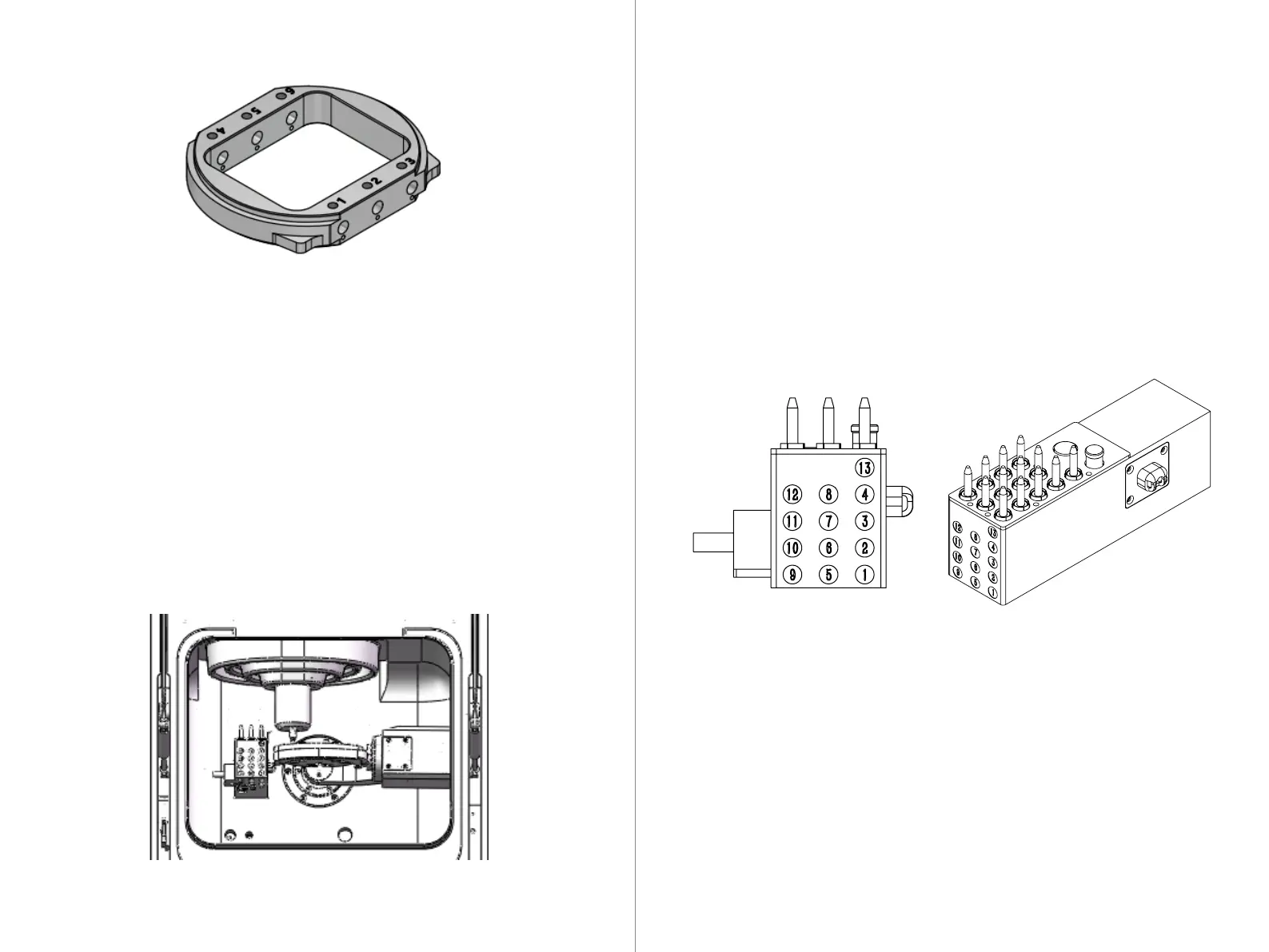
8.4.1 Tool Installation Position
Tool replacement can be operated through the CNC interface. This is applicable
when the tool reaches its maximum lifespan but remains clamped to the
spindle. In such cases, an automatic or manual tool change is needed to remove
the milling cutter.
Tool Lifespan: The CNC system will record information about the tool's lifespan.
When the tool reaches its maximum usage limit, it should be replaced promptly.
After replacing the tool, remember to reset the recorded information in the CNC
system. Refer to the CNC guide for specific instructions.
8.4.2 Automatic or Manual Tool Change
8.4 Tool Installation
1. Open the equipment access door and click on the material loading position in CNC 3.
2. Loosen the three bolts used to secure the chuck body with an Allen wrench,
but do not remove them.
3. If there is a material tray installed, remove it and use a brush to clean the
chuck, ensuring there are no residues.
4. Install the BK-1 chuck body with the square material from top to bottom into
the workspace chuck.
5. After installation, use a wrench to tighten the bolts to secure the material,
ensuring it is firmly fixed and ready for machining.
Installing square material in the workspace: