© UPLIFT Desk • 800-349-3839 • 512-614-3152 • info@upliftdesk.com • upliftdesk.com
7
B.
Place the leg assembly so that the Side Bracket is centered between the front and back edges of the
desktop and approximately 1/2” in from the side edge of the desktop.
C.
Make a pencil mark in the center of each of the Side Bracket holes and the
Crossbar End hole. Then move the leg assembly out of the way and drill
pilot holes using a 1/8” drill bit. IMPORTANT: DRILL NO DEEPER THAN
1/2”. To ensure this, we recommend wrapping a piece of tape around
your drill bit 1/2” from the tip. Stop drilling just before the tape touches
the desktop.
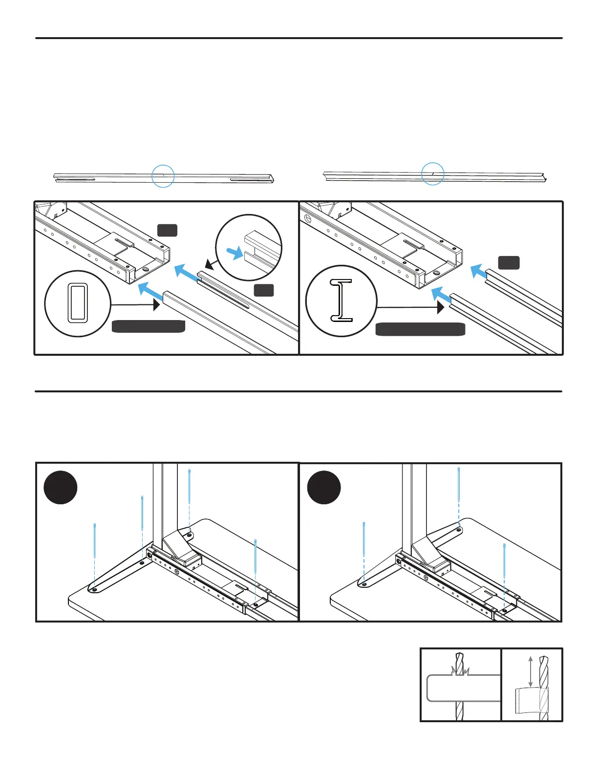
A. If you have “tube shape” Crossbar Rails (P6),
position them so that the center indicator marks
are facing up and side slots face inward as shown
here. Slide the Crossbar Rails into the Crossbar
End (P5) of the Leg assembly shown with the
center indicator marks facing up. This will be
the right side Leg of your desk when it is ipped
upright.
P5
P6
Tube Shape
Center indicator mark
Center indicator mark
Step 4 - Crossbar Rail Installation
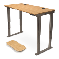
B. Place your desktop upside down on a debris-free blanket or carpet. If your desktop has threaded inserts
or pre-drilled holes, they should be visible and facing up.
A. If you have “I-beam shape” Crossbar Rails (P6),
slide the Crossbar Rails into the Crossbar End
(P5) of the Leg assembly shown with the center
indicator marks facing up. This will be the right
side Leg of your desk when it is ipped upright.
P6
I-Beam Shape
Step 5 - Drill Desktop Holes (If applicable)
• Skip this step and proceed to Step 6 if your desktop has threaded metal inserts or pre-drilled holes.
A You will be drilling holes for the rst leg assembly now, at a later step you will be drilling holes for the
other leg assembly.
0.5”
Tape
Center indicator mark
Center indicator mark