© UPLIFT Desk • 800-349-3839 • 512-614-3152 • info@upliftdesk.com • upliftdesk.com
8
H4 b
H4 a
C3
C4 C5
C9
H4a
H7
C6
H1 H2 H3
H5
H4b
H6
C7
C3
C4 C5
C9
H4a
H7
C6
H1 H2 H3
H5
H4b
H6
C7
Machine Screw: at end
Wood Screw: pointy end
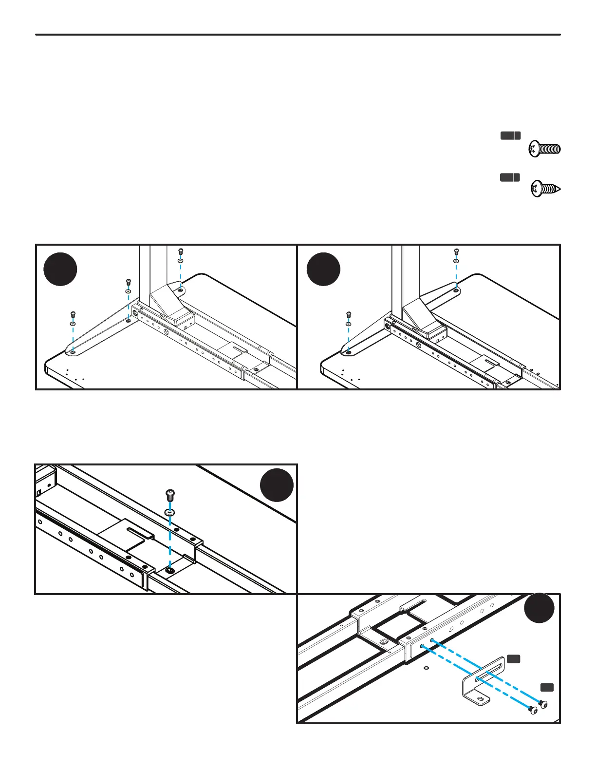
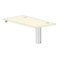
Step 6 - Leg Assembly Attachment
A. Align the holes in the Side Bracket with the holes on the desktop. When adjusting the location of the leg
assembly on your desktop, lift it up to move it instead of sliding it. This will help protect your desktop and
keep the pre-installed rubber grommets in the Side Bracket and Crossbar End from becoming dislodged.
If they do become dislodged, they can be easily reinserted.
B. IMPORTANT! Determine the correct screws to use based on whether your desktop has threaded metal
inserts or pre-drilled holes.
• For desktops that have threaded metal inserts: use the 3/4”
Machine Screws (H4b) and Washers (H5) for the following steps.
Do not use the wood screws with the pointy end.
• For desktops that have pre-drilled holes: use the 3/4” Wood
Screws (H4a) and Washers (H5) for the following steps.
C. Use a Phillips Head Screwdriver and the screws and washers determined above to attach the Side Bracket
to the desktop, but do not tighten the screws completely yet.
C-Frame
1. Use one of the screws and washers determined
above to fasten the Crossbar End to the desktop
as shown in the image below, but do not tighten
completely.
T-Frame
If you drilled pilot holes in Step 5, use one screw
and washer to attach the Crossbar End to the
desktop, but do not tighten completely.
If your desktop has pre-drilled holes or threaded
metal inserts, proceed with Steps 1 and 2 be-
low:
1. There is a left and a right Crossbar End Adapter
(P3). Select the one that can be positioned as
shown and attach it to the Crossbar End (P5) in
the orientation shown using two M8x10 Machine
Screws (H7), but do not tighten the screws yet.
P3
H7