Section 2 - Service and Repair Hydraulic Pressure Settings
113101-000 MX15 / MX19 | Service Manual Page 2-17
C
OUNTERBALANCE
V
ALVES
1. Operate the machine for 10-15 minutes to bring the hydraulic fluid up to normal operating temperature.
2. Remove the test port cap and install a pressure gauge capable or reading up to 250 bar (3500 psi)
onto the test port.
3. Lift the machine and support the chassis with jackstands so that the drive wheels are off the ground.
4. Loosen the locknuts on Counterbalance Valves.
5. With the Chassis Key Switch on DECK and the Drive/Lift Switch in DRIVE depress the Interlock Lever
and slowly pull the Control Handle to REVERSE to drive the wheels.
6. Adjust the Forward Counterbalance Valve by turning the adjustment screw until the pressure gauge
indicates 55 bar (800 psi).
7. Slowly push the Control Handle to FORWARD to drive the wheels.
8. Adjust the Reverse Counterbalance Valve by turning the adjustment screw until the pressure gauge
indicates 55 bar (800 psi).
9. Check the settings by slowly moving the Control Handle FORWARD, then REVERSE, checking the
gauge to ensure that the pressures are properly set. Readjust as needed.
10. Tighten the locknuts on the valves to 8 N-m (6 ft./lbs.).
11. Remove the pressure gauge and replace the test port cap.
12. Remove the blocks and lower the machine to the ground.
13. Check for proper operation of the drive system.
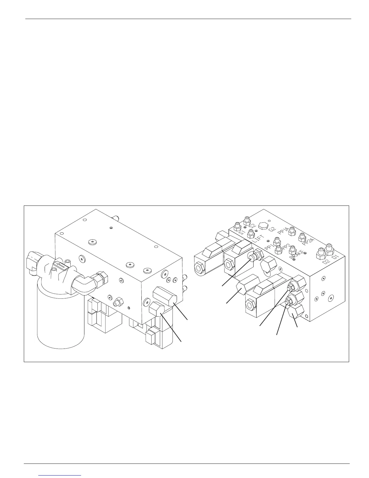
Figure 2-11:
Hydraulic Manifold Test Ports, from right side
Front
Bottom
Right
To p
(Mounting Surface)
Left
Rear
Forward
Counterbalance
Valve
Reverse
Counterbalance
Valves
Lift Relief
Valve
Main Relief
Valve
Test Port
Steering Relief
Valve
Flow Divider
Valve