Section 3 - Service & Repair Supporting Elevating Assembly
505115-000 Pa
e 3-3
3-1 S
UPPORTING
E
LEVATING
A
SSEMBLY
WARNING
!
!
Never perform service on the work platform in the elevating assembly area while platform is elevated
without first blocking the elevating assembly.
DO NOT stand in elevating assembly area while deploying or storing brace.
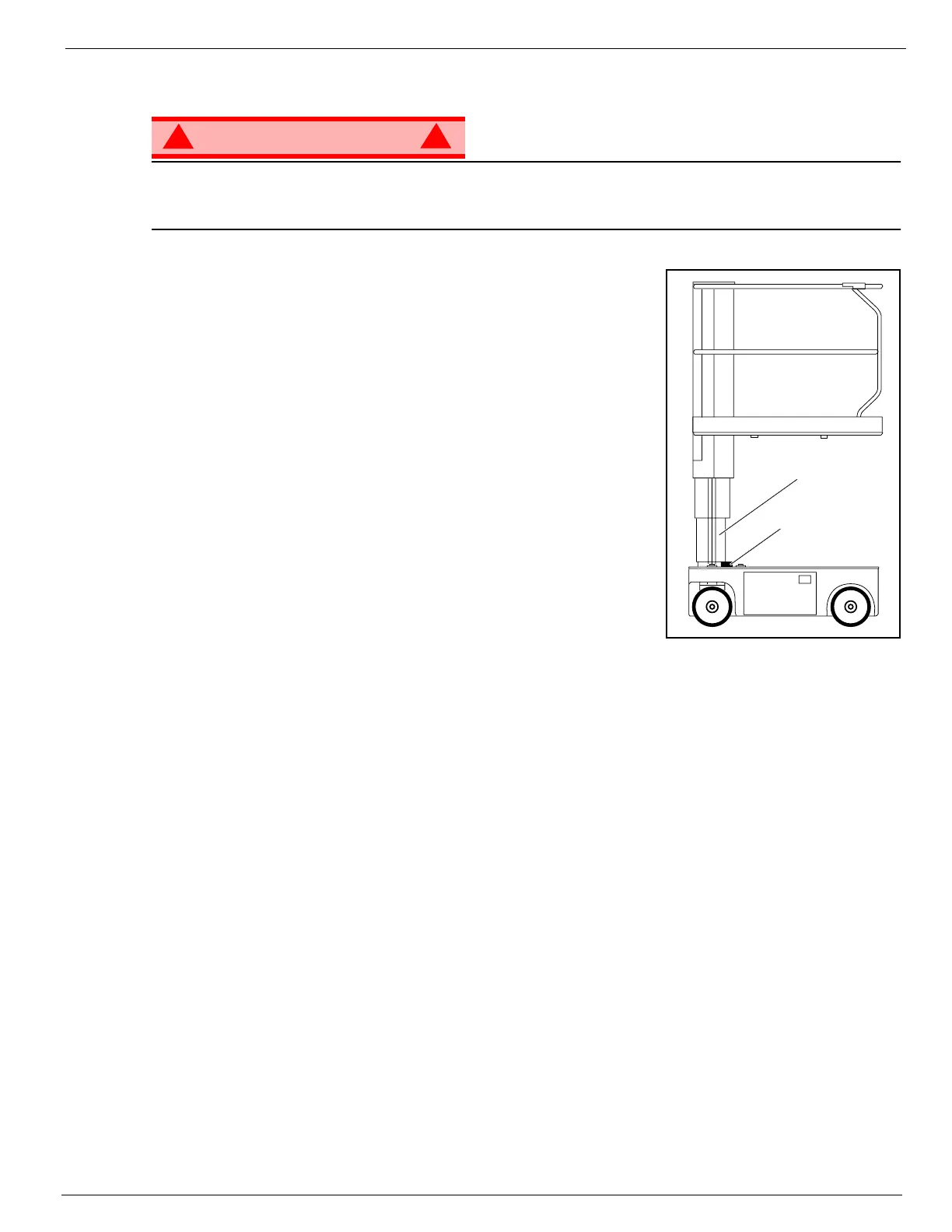
Figure 3-1: Supporting Elevating Assembly
I
NSTALLATION
1. Park the Work Platform on firm level ground.
2. Verify Platform Emergency Stop Switch is ON.
3. Turn Chassis Key Switch to CHASSIS.
4. Position Chassis Lift/Lower Switch to UP and elevate Platform
approximately 1.2m (4 feet).
5. Place a wood block, 5cm x 10cm x 46cm (2 in. x 4 in. x 18 in.) long
between the #2 Mast and Chassis just behind the Mast Assembly.
6. Push Chassis Lift Switch to DOWN position and gradually lower
Platform until the #2 Mast is supported by the block.
R
EMOVAL
1. Push Chassis Lift Switch to UP position and gradually raise Platform
until wood block can be removed.
2. Remove block.
3. Push Chassis Lift Switch to DOWN position and completely lower
Platform
Number 2 Mast
Wood Block

 Loading...


