Pa
e 1-1
Section 1
INTRODUCTION
1.1 I
NTRODUCTION
P
URPOSE
The purpose of this service and parts manual is to provide instructions and illustrations for the
operation and maintenance of the TM12 manufactured by UpRight.
S
COPE
The manual includes procedures for proper operation, maintenance, adjustment, and repair of
the TM12 as well as recommended maintenance schedules and troubleshooting.
1.2 G
ENERAL
D
ESCRIPTION
The TM12 consists of the platform, controller, elevating assembly, power module, control mod-
ule, and chassis.
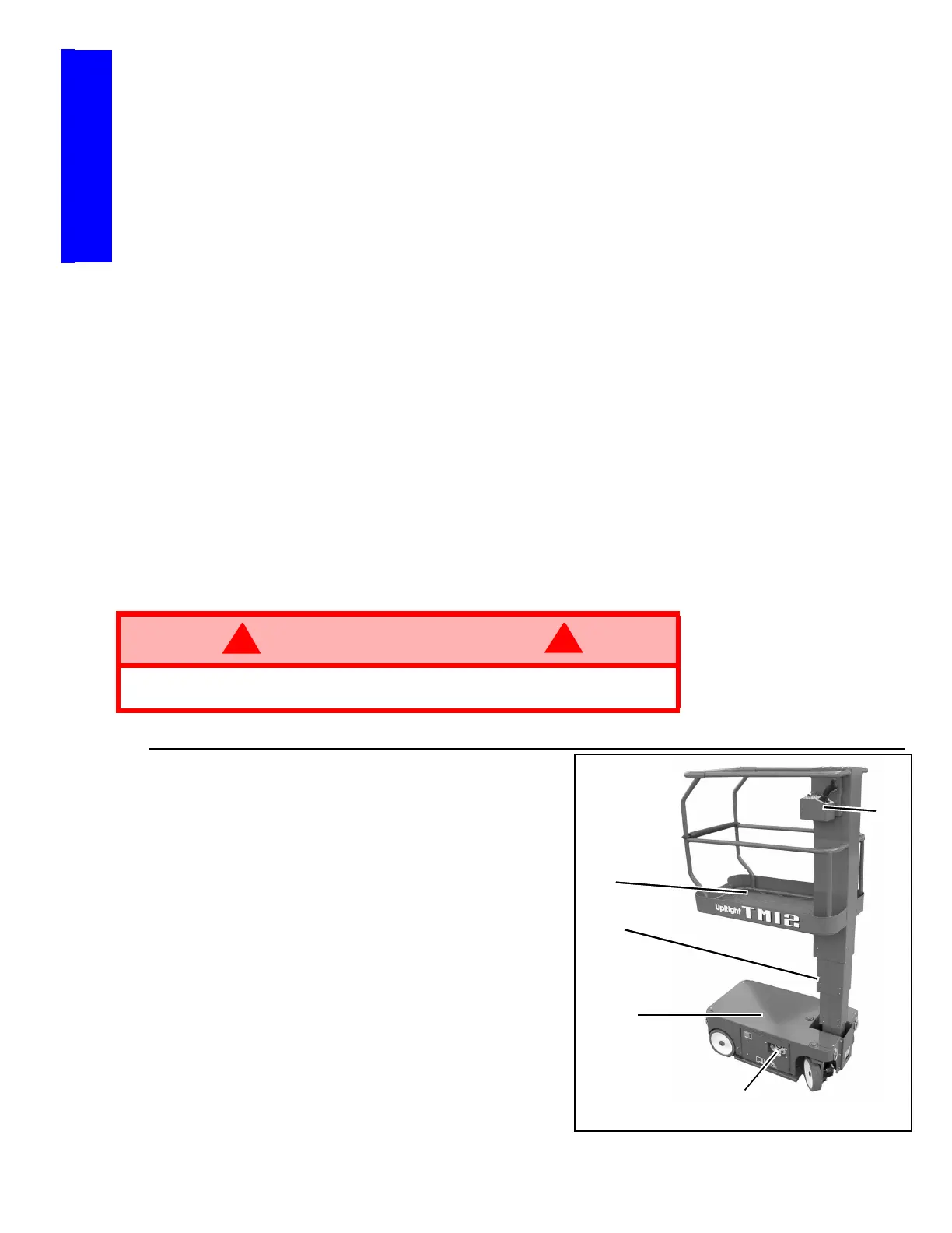
Figure 1-1:
TM12 Work Platform
P
LATFORM
The platform has a reinforced steel floor, 1.11
m (43.75 inch) high guardrails with midrail, 6
inch (152 mm) toeboards, and an entrance
gate at the rear of the platform.
P
LATFORM
C
ONTROLLER
The platform controller contains the controls
to operate the machine. It is located at the
front of the platform. A complete explanation
of control functions can be found in Section 2.
E
LEVATING
A
SSEMBLY
The platform is raised and lowered by the ele-
vating assembly. The hydraulic pump, driven
by an electric motor, powers the cylinder.
Solenoid operated valves control raising and
lowering.
WARNING
!
!
DO NOT use the work platform without guardrails properly assembled and in
place.
1.Platform
2.Platform Controller
3.Elevating Assembly
4.Chassis Controls
5.Chassis
1
2
3
4
5

 Loading...


