14
3.
Insofar as is practical, close all building doors and
windows and all doors between the space in which the
appliances remaining connected to the common venting
system are located and other spaces of the building.
Turn on clothes dryers and any appliance not connected
to the common venting system. Turn on any exhaust
fans, such as range hoods and bathroom exhausts, so
they will operate at maximum speed. Do not operate a
summer exhaust fan. Close fi replace dampers.
4.
Place in operation the appliance being inspected. Follow
the lighting instructions. Adjust thermostat so appliance
will operate continuously.
5.
Test for spillage at the draft hood relief opening after
5 minutes of main burner operation. Use the fl ame of
a match or candle, or smoke from a cigarette, cigar or
pipe.
6.
After it has been determined that each appliance
remaining connected to the common venting system
properly vents when tested as outlined above, return
doors, windows, exhaust fans, fi replace dampers and
any other gas-burning appliance to their previous
conditions of use.
7.
Any improper operation of the common venting system
should be corrected so the installation conforms with
the National Fuel Gas Code, ANSI Z223.1/NFPA 54.
When resizing any portion of the common venting
system, the common venting system should be resized
to approach the minimum size as determined using the
appropriate tables in Chapter 13 of the National Fuel
Gas Code, ANSI Z223.1/NFPA 54.
Vent connectors serving appliances vented by natural
draft shall not be connected into any portion of
mechanical draft systems operating under positive
pressure.
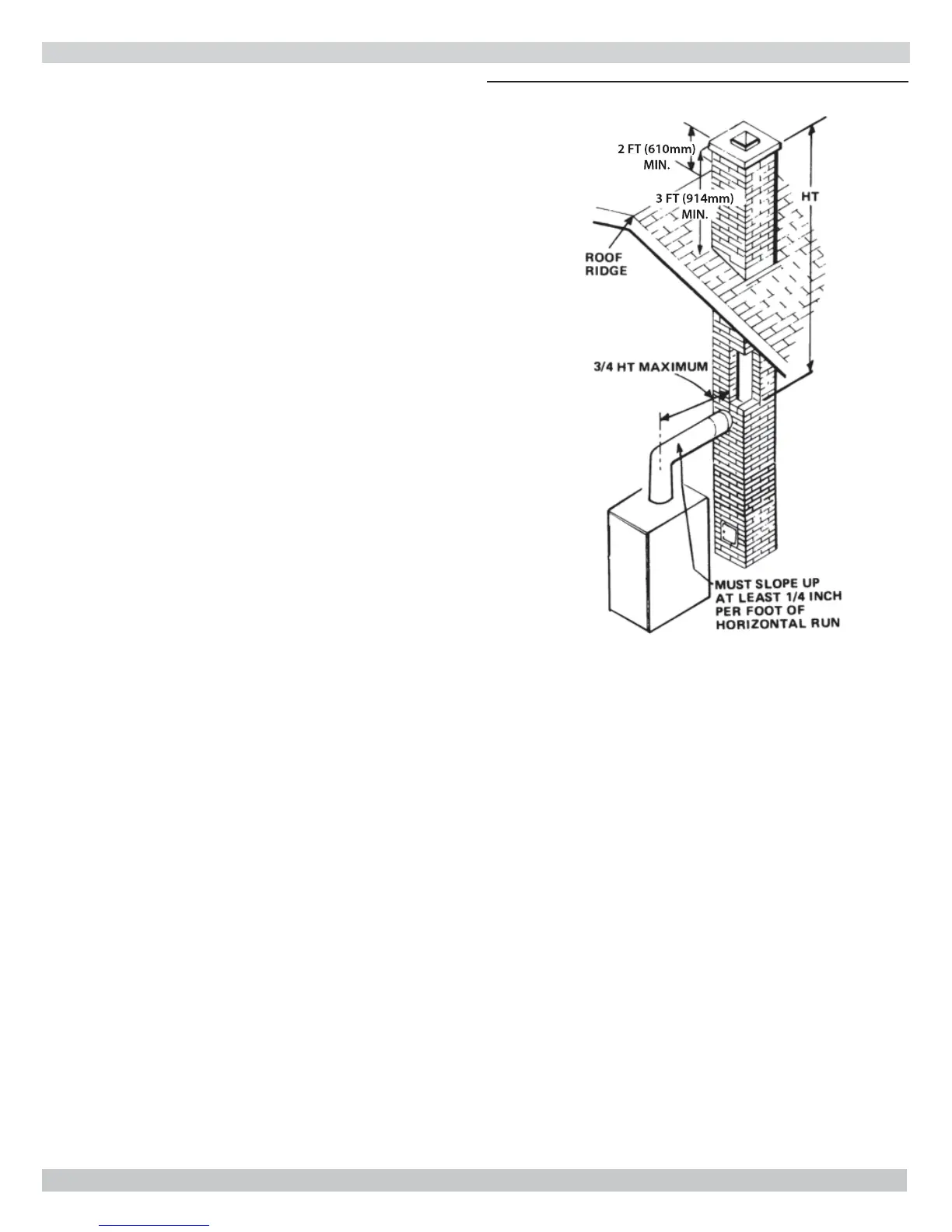
CHIMNEY AND VENT PIPE CONNECTION
Figure 9 - Typical Masonry Chimney Requirements