20
CHECKING AND ADJUSTING
Adjust Pilot Burner
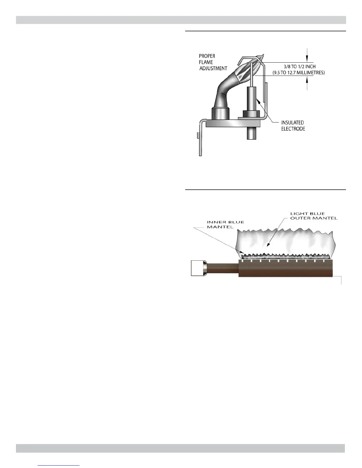
Pilot fl ame should surround 3/8” to 1/2” of pilot sensor. See
Figure 15.
To adjust Flame.
1.
Remove screw cover over pilot adjusting screw. See
Figure 14.
2.
Insert small screwdriver and adjust fl ame as needed.
Turn screw counterclockwise to increase fl ame, clock-
wise to decrease.
3.
Replace screw cover over pilot adjusting screw.
Main Burners
• Main burners do not require primary air adjustment and
are not equipped with primary air shutters.
• Main burner fl ames form sharp blue inner cones in
softer blue outer mantel, with no yellow. Remain still
when observing main burner fl ames.
• Check main burner orifi ces, burner throat and fl ame
ports for dust and lint obstruction if fl ame appearance
is not correct.
• Remove rollout shield if necessary to observe main
burner fl ames. See Figure 16.
• Replace rollout shield after observation.
Gas Valve Safety Shutdown Test
1.
Test ignition system safety shutoff device after placing
boiler in operation.
2.
Boilers equipped with intermittent ignition, with
main burners fi ring, disconnect ignition cable from
intermittent pilot control box. Gas valve will shut off
main burners.
3.
TURN OFF ELECTRIC POWER to boiler before
reconnecting ignition cable, to prevent electric shock.
Figure 15 - Pilot Burner
Figure 16 - Main Burner