PAGE 4
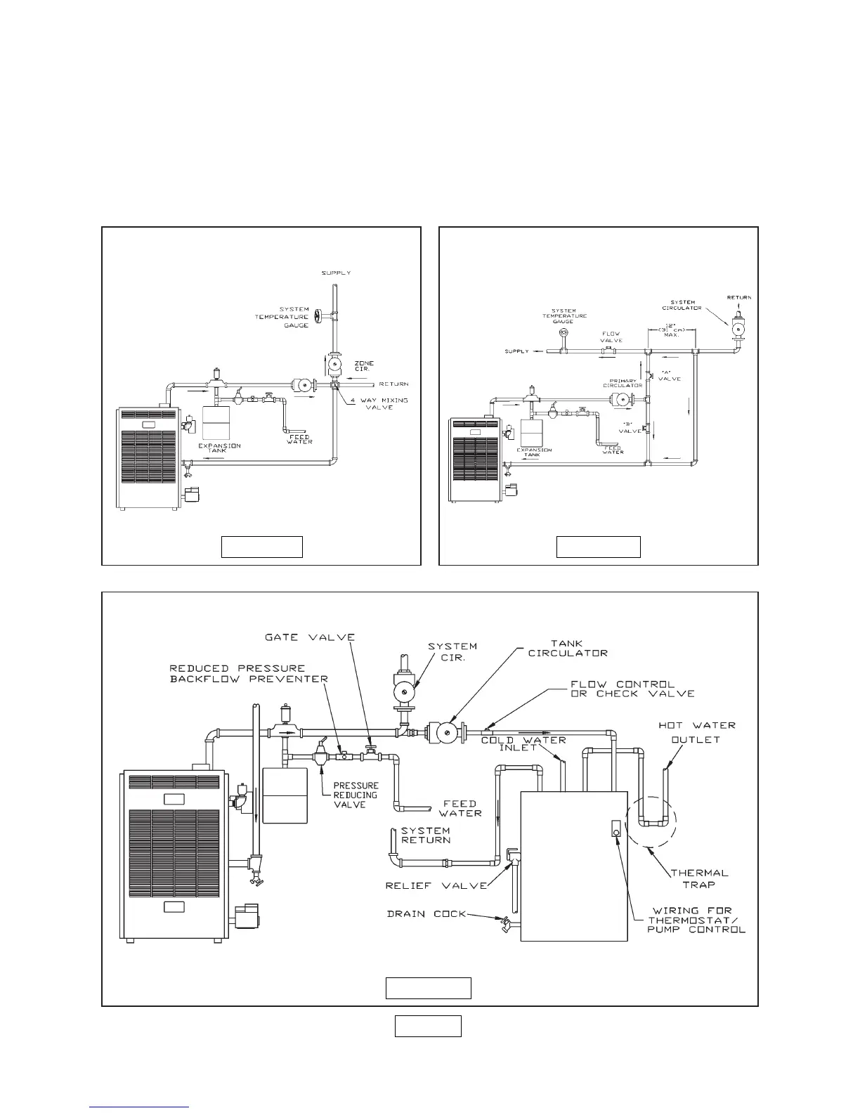
FIGURE 4
FIGURE 5
FIGURE 6
MIXING-VALVE PIPING
PRIMARY SECONDARY PIPING
WITH BYPASS
6. Note: When using a 4-way mixing valve, set control knob until desired temperatures are
met. See instruction supplied with valve.
7. Bypass loop piping must be the same size piping as the supply and the return.
8. Typical installation using circulators is shown in figure 6 on page 4.
9. Typical installation using zone valves is shown in figure 7, below.
10. For further piping information refer to the I=B=R installation and piping guide.