8
NEW CONSTRUCTION ASSEMBLY INSTRUCTIONS
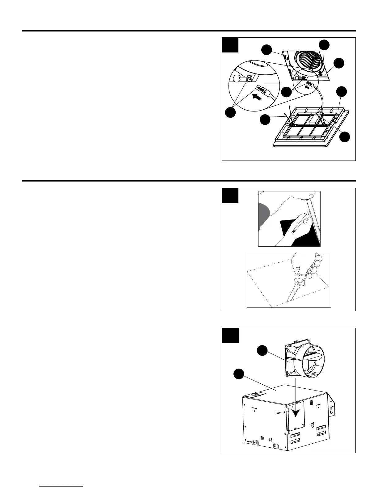
EXISTING CONSTRUCTION ASSEMBLY INSTRUCTIONS
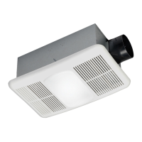
7. For the LED light connection, plug in the connector
(7.1) from the grille (B) into the fan housing (A) as
shown.
Pinch the mounting springs (7.2) on the grille (B) and
insert them into the narrow rectangular slots (7.3)
inside the fan housing (A). Push the grille (B) up
toward the ceiling.
BEFORE INSTALLATION – Turn off power source. Review
all safety precautions. Remove old fan.
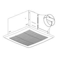
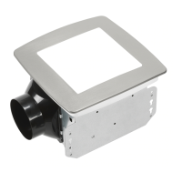
1. Measure the opening to ensure it is large enough
to accommodate the new fan housing (A)
(7.5 in. x 7.25 in.).
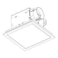
If this fan is not replacing an old fan, be sure to cut a
7.5 in. x 7.25 in. opening for the fan housing (A).
MAKE SURE THE 7.25 IN. SIDE OF THE OPENING
IS FLUSH WITH THE JOIST FOR INSTALLATION
FROM BELOW.
2. Attach the duct connector (C) to the fan housing (A).
7
4
5
6
7
8
9
1
0
1
1
1
7.50"
7.25
"
1
7.1
7.1
7.2
7.2
A
7.3
B
7.3
3
A
C