vacon 10 api vacon • 7
24-hour support +358 (0)201 212 575 • Email: vacon@vacon.com
3
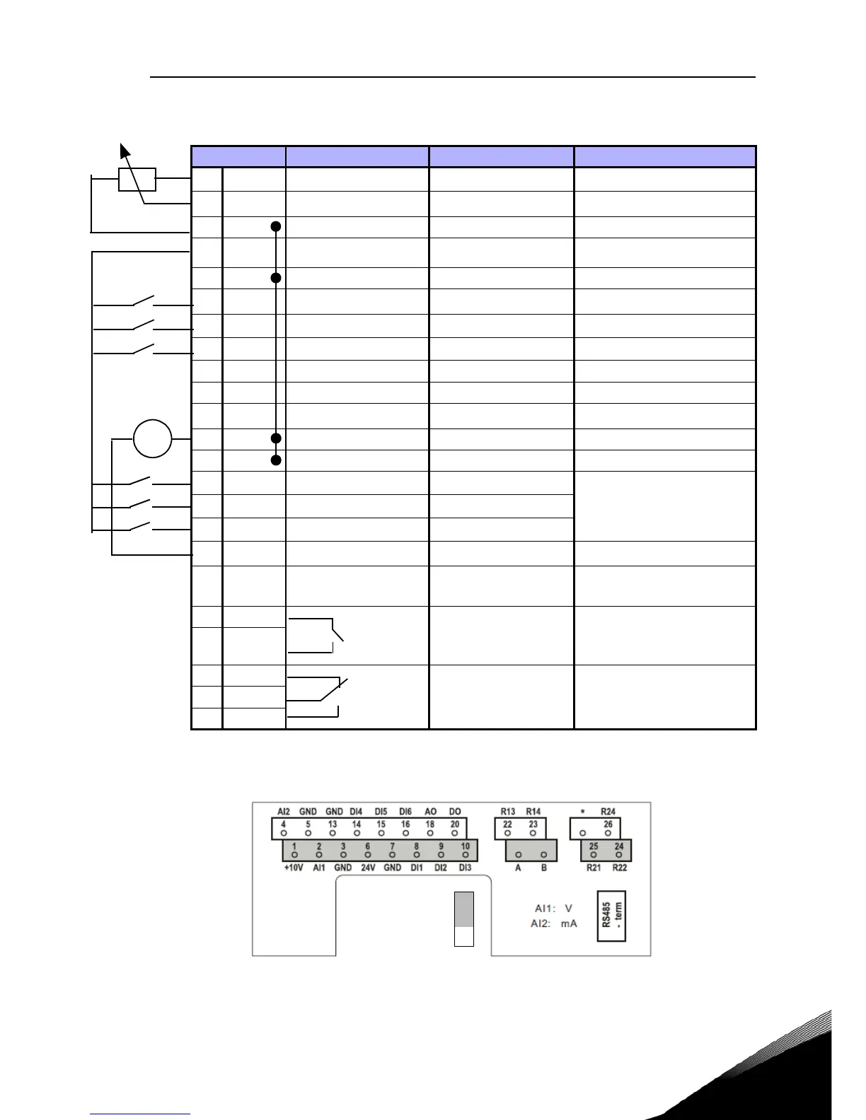
3. CONTROL I / O AND TERMINALS
Figure 3.1: Vacon 10 I / O
Terminal Signal Factory preset Description
1 +10Vref Ref. voltage out Maximum load 10 mA
2 AI1 Analog signal in 1
Freq. reference
P)
0 - 10 V Ri = 200 k
3 GND I/O signal ground
6 24Vout 24V output for DI's
%, max. load 50 mA
7 GND I/O signal ground
8 DI1 Digital input 1
Start forward
P)
0 - +30 V Ri = 12 k min
9 DI2 Digital input 2
Start reverse
P)
10 DI3 Digital input 3
Fault reset
P)
A A RS485 signal A FB Communication Negative
B B RS485 signal B FB Communication Positive
4 AI2 Analog signal in 2
PI actual value
P)
0(4) - 20 mA, Ri = 200
5 GND I/O signal ground
13 GND I/O signal ground
14 DI4 Digital input 4
Preset speed B0
P)
0 - +30 V Ri = 12 k
(min)
15 DI5 Digital input 5
Preset speed B1
P)
16 DI6 Digital input 6
External fault
P)
18 AO Analog Output
Output frequency
P)
0(4) - 20 mA, RL = 500
20 DO Digital signal out
Active = READY
P)
Open collector, max.
load 48V/50mA
22 RO 13 Relay out 1
Active = RUN
P)
Max. switching load:
250Vac/2A or 250Vdc/
0,4A
23 RO 14
24 RO 22 Relay out 2
Active = FAULT
P)
Max. switching load:
250Vac/2A or 250Vdc/
0,4A
25 RO 21
26 RO 24
Table 3.1: Vacon 10 default I/O configuration and connections
P) = Programmable function, see parameter lists and descriptions,
chapters 5.
 Loading...


