monitoring & parameters vacon • 13
24-hour support +358 (0)201 212 575 • Email: vacon@vacon.com
5
5. MONITORING & PARAMETERS
NOTE! This guide is for Vacon 10 standard application, if you need description of
parameters in detail, please download the application manual on: www.vacon.com
-> downloads.
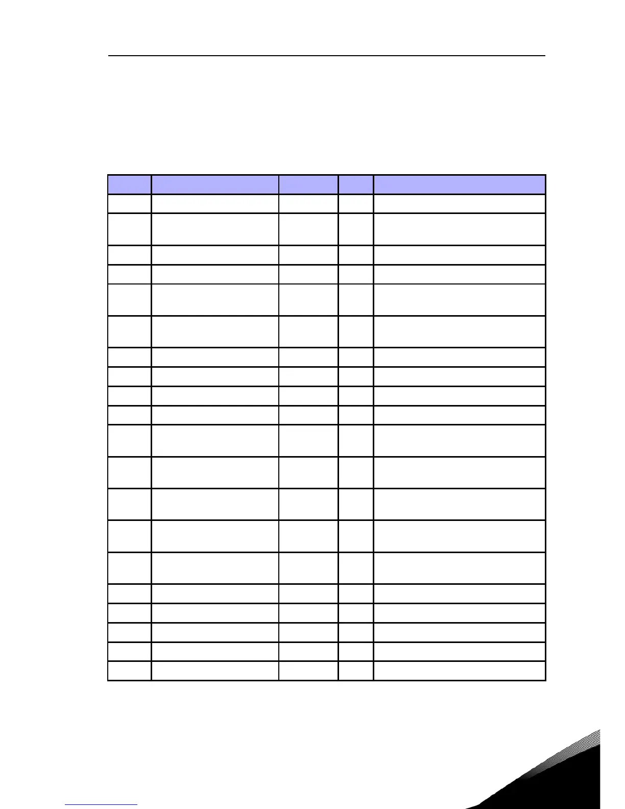
5.1 Monitoring values
Code Monitoring signal Unit ID Description
V1.1 Output frequency Hz 1 Output frequency to motor
V1.2 Frequency reference Hz 25
Frequency reference to motor con-
trol
V1.3 Motor speed rpm 2 Calculated motor speed
V1.4 Motor current A 3 Measured motor current
V1.5 Motor torque % 4
Calculated actual / nominal torque
of the motor
V1.6 Motor Power % 5
Calculated actual / nominal power
of the motor
V1.7 Motor voltage V 6 Motor voltage
V1.8 DC-link voltage V 7 Measured DC-link voltage
V1.9 Drive temperature °C 8 Heatsink temperature
V1.10 Motor temperature % 9 Calculated motor temperature
V2.1 Analog input 1 % 59
AI1 signal range in percent of used
range
V2.2 Analog input 2 % 60
AI2 signal range in percent of used
range
V2.3 Analog output % 81
AO signal range in percent of used
range
V2.4
Digital input status DI1,
DI2, DI3
15 Digital input status
V2.5
Digital input status DI4,
DI5, DI6
16 Digital input status
V2.6 RO1, RO2, DO 17 Relay / digital output status
V4.1 PI setpoint % 20 Regulator setpoint
V4.2 PI feedback value % 21 Regulator actual value
V4.3 PI error % 22 Regulator error
V4.4 PI output % 23 Regulator output
Table 5.1: Vacon 10 monitoring signals
 Loading...


