UK: VACON
®
100 drive supply switch vacon • 5
24-hour support +358 (0)201 212 575 • Email: vacon@vacon.com
uk
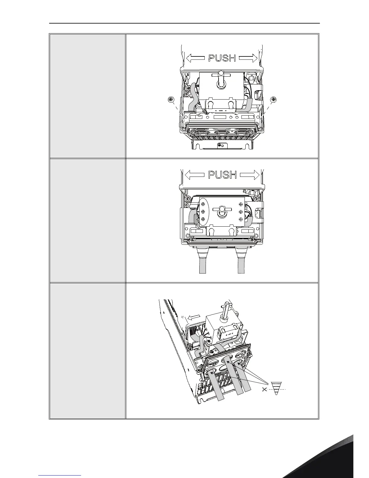
7
Attach the drive supply
switch screws.
8
Tighten the supply cable
screws on the drive supply
switch according to the
tightening torques given in
Table 1. Please also check
the tightening of the
factory-installed cable
connection screws on the
right side of the drive
supply switch.
9
MR4: Lead the data
cable “D” under the drive
supply switch and attach it.
MR5-MR7: Lead the data
cable around the drive
supply switch to the
control terminal.
NOTE 1! Protect the data
cable as close to the
terminal as possible with
the cable insulation tube!
NOTE 2! See detailed
cable installation
instructions in the
VACON
®
100 installation
manual!