OneLINK For RoboSHOT HDMI Cameras
OneLINK For RoboSHOT HDMI Cameras Page 7 of 20
B
ASIC
S
YSTEM
C
ONFIGURATION
:
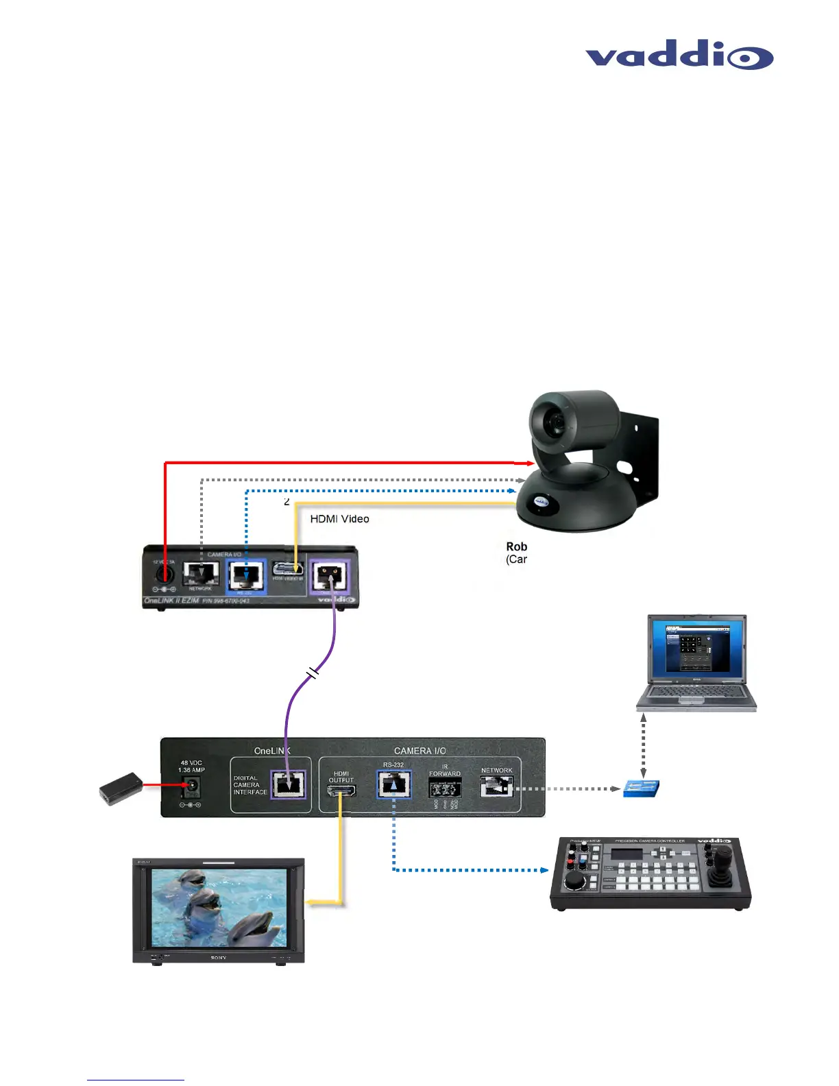
The OneLINK HDMI EZIM and OneLINK HDMI Interface are connected to each other with one Cat-5e or better
cable plugged into the purple “OneLINK” ports at either end.
Installation
Step 1: Connect the 1’ (305mm) cables from the OneLINK EZIM to the camera. There will be a power cable, Cat-
5e patch cables for RS-232 and Network and an HDMI M to M cable.
Step 2: Connect the OneLINK ports with a quality Cat-5e cable.
In noisier RF or EMF environments - when in doubt,
use shielded Cat-6 cable. Cable distance between the OneLINK EZIM and Interface is a maximum of 328 feet (100 m).
Step 3: At the OneLINK Interface, Connect the HDMI Output to the video destination (monitor, switcher, console controller,
etc…), connect the control sources RS-232 or network control or both. Connect the 48 VDC, 1.36 Amp power supply to the
OneLINK HDMI Interface. The camera will boot up, calibrate the direct drive motors and in a few moments, the camera is ready
for operation.
Please see the camera manual for setup and configuration of the video and other camera settings.
Diagram: Basic Connectivity of the OneLINK System
RoboSHOT 30 HDMI Camera
(Cameras are sold separately)
RS-232
HDMI Video
Simulated dolphins in a simulated
dolphin pool
ProductionVIEW™ Precision
Camera Controller
Powe
OneLINK Digital Bus
Video, Power and Control up to
328’
100m
on Cat-5e/6 Cable
48 VDC,
1.36 Amp
Power Supply
Ethernet
PC for Camera
Configuration and
Control
OneLINK HDMI Interface
OneLINK EZIM
Camera Interface
RS-232 Cat-5e
HDMI
Video
Ethernet
Network
Switch
Ethernet