Set-up 5
0020297937_01 aroTHERM plus Installation and maintenance instructions 119
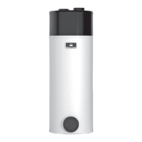
Condition: Especially for wall installation
▶ Ensure that the wall fulfils the static requirements. Please
note the weight of the unit mounting bracket (accessory)
and the outdoor unit.
▶ Avoid choosing an installation position which is near to a
window.
▶ Please note the noise emissions. Maintain sufficient
clearance from reflective building walls.
▶ Route the hydraulic lines and electrical wires. Provide a
wall duct.
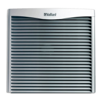
Condition: Especially for flat-roof installation
▶ Only install the product in buildings with a solid construc-
tion and that have cast concrete ceilings throughout.
▶ Do not install the product in buildings with a wooden
structure or with a lightweight roof.
▶ Select an installation site that is easily accessible so
that foliage or snow can be regularly removed from the
product.
▶ Select an installation site at which the air inlet is not af-
fected by strong winds. Position the unit as crosswise to
the main direction of wind as possible.
▶ If the installation site is not protected against the wind,
you should plan to set up a protective wall.
▶ Please note the noise emissions. Maintain sufficient
clearance from adjacent buildings.
▶ Route the hydraulic lines and electrical wires. Provide a
wall duct.
5.7 Preparing for fitting and installation
Danger!
Risk of death caused by fire or explosion
if there is a leak in the refrigerant circuit!
The product contains the combustible refri-
gerant R290. In the event of a leak, escaping
refrigerant may mix with air to form a flam-
mable atmosphere. There is a risk of fire and
explosion.
▶ Keep all ignition sources away from the
product. In particular, open flames, hot
surfaces with temperatures above 370 °C,
electrical devices that are not free from
electrical sources, static discharges.
▶ Observe the basic safety regulations before starting
work.
▶ Ensure that all of the electric tools that are used when
working in the protective zone are free of ignition
sources.
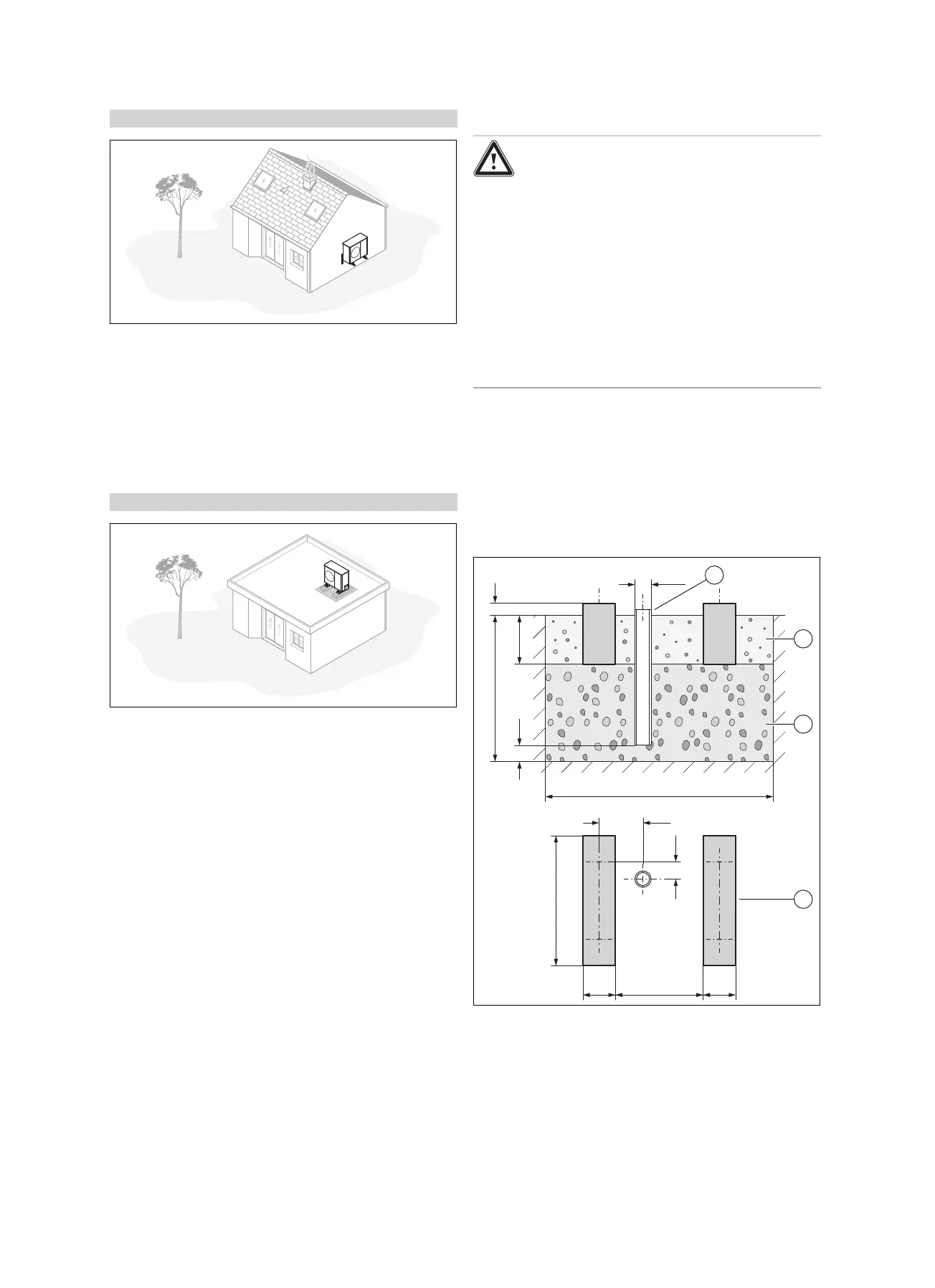
5.8 Ground installation
5.8.1 Creating a foundation
800
200 540 200
1400
Ø100
270
300100
AB
106
2
3
4
1
▶ Dig a hole in the ground. The recommended dimensions
can be found in the figure.
▶ Insert a downpipe (1) to divert the condensate.
▶ Add a layer of water-permeable coarse rubble (3).
▶ Calculate the depth (A) in accordance with local condi-
tions.