Appendix
0020297937_01 aroTHERM plus Installation and maintenance instructions 135
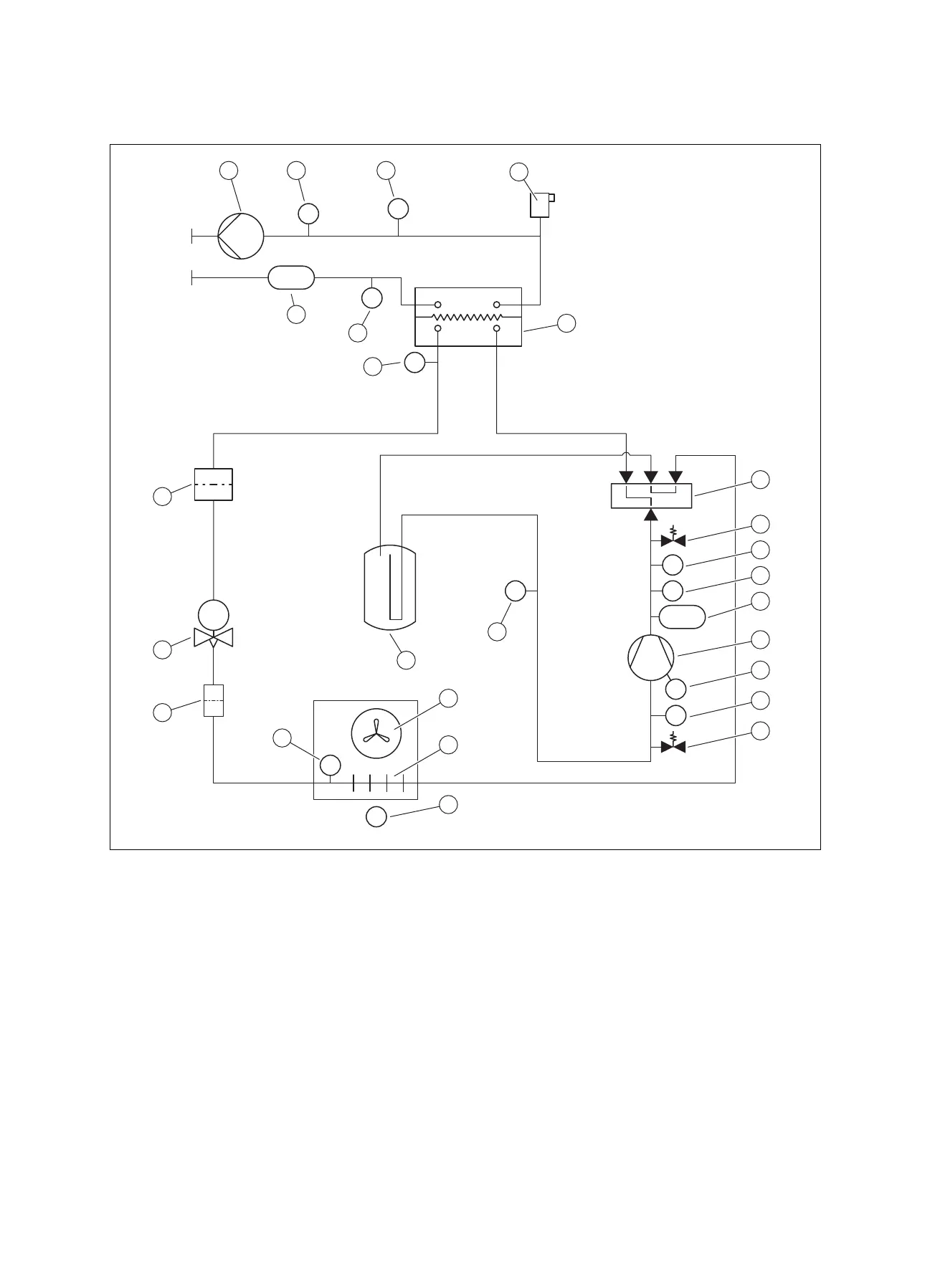
B Safety devices
TI
PTPT
PZHH
TCE
PT
TI
TI
TI
TI
TI
TI
T
FS
18
17
5
21
22
23
20
1 2 3
4
6
7
8
9
10
11
12
13
14
19
16
15
24
25
26
1 Heating pump
2 Temperature sensor, heating flow
3 Pressure sensor, in the heating circuit
4 Automatic air vent, in the heating circuit
5 Condenser (heat exchanger)
6 4-port diverter valve
7 Maintenance connection, in the high-pressure area
8 Temperature sensor, behind the compressor
9 Pressure sensor, in the high-pressure area
10 Pressure switch, in the high-pressure area
11 Compressor, with refrigerant separator
12 Temperature monitor, on the compressor
13 Temperature sensor, in front of the compressor
14 Maintenance connection, in the low-pressure area
15 Pressure sensor, in the low-pressure area
16 Refrigerant buffer
17 Fan
18 Evaporator (heat exchanger)
19 Temperature sensor, air inlet
20 Temperature sensor, at the evaporator
21 Filter
22 Electronic expansion valve
23 Filter/dryer
24 Temperature sensor, behind the condenser
25 Temperature sensor, heating return
26 Flow rate sensor
 Loading...