Appendix
138 Installation and maintenance instructions aroTHERM plus 0020297937_01
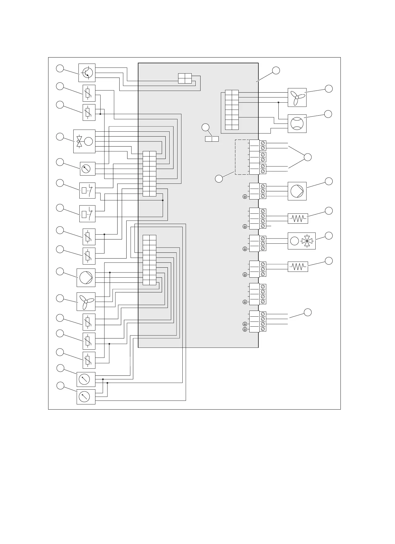
C.3 Wiring diagram, sensors and actuators
X11
X100 / X106
X27
X25
S20
S21
BUS
5
6
3
4
1
2
L
N
M
p
X21
X22
1
7
8
2
918
17
16
15
14
13
12
11
10
3
4
5
6
12
1
7
8
2
919
20
18
17
16
15
14
13
12
11
10
3
4
5
6
X16
3
1
2
L
N
X13
L
N
X15
3
4
1
2
S
L
N
X14
S
L
N
X1
L
N
X24
6
4
3
2
1
5
7
8
9
12
11
10
13
14
15
16
3
1
2
3
1
2
3
4
1
2
3
4
1
2
p
˽
˽
˽
˽
˽
M
˽
˽
˽
31
42
p
p
2
3
4
6
5
22
23
25
24
21
20
1
7
8
9
19
18
17
16
15
14
13
12
11
10
26
27
1 HMU PCB
2 Actuation for fan 2 (only for product VWL 125/6 and
VWL 155/6)
3 Flow rate sensor
4 Connection to the INSTALLER BOARD PCB
5 Heating pump power supply
6 Crankcase heating
7 4-port diverter valve
8 Condensate tray heater
9 Connection to the INSTALLER BOARD PCB
10 Pressure sensor, in the low-pressure area
11 Pressure sensor, in the heating circuit
12 Temperature sensor, on the heating flow
13 Temperature sensor, on the heating return
14 Temperature sensor, at the air inlet
15 Actuation for fan 1
16 Actuation for the heating pump
17 Temperature sensor, behind the compressor