Start-up 8
0020297937_01 aroTHERM plus Installation and maintenance instructions 125
N
L3
L2
L1
N
L
1
2
3
4
5
L1
L2
L3
N
X211
X210
X200
1
2
L
N
L
N
4
2
3
1
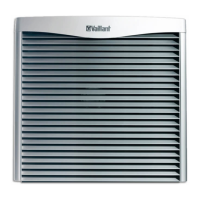
2. Install two disconnectors for the product, as shown in
the figure.
3. Use a 5-pole power supply cable (from the heat pump
electricity meter) and a 3-pole power supply cable (from
the household electricity meter). Route this from the
building and through the wall duct to the product.
4. Connect the 5-pole power supply cable to connection
X200 in the electronics box.
5. Remove the 2-pole bridge from the X210 connection.
6. Connect the 3-pole power supply cable to connection
X211.
7. Use the strain relief clamps to secure the power supply
cables in place.
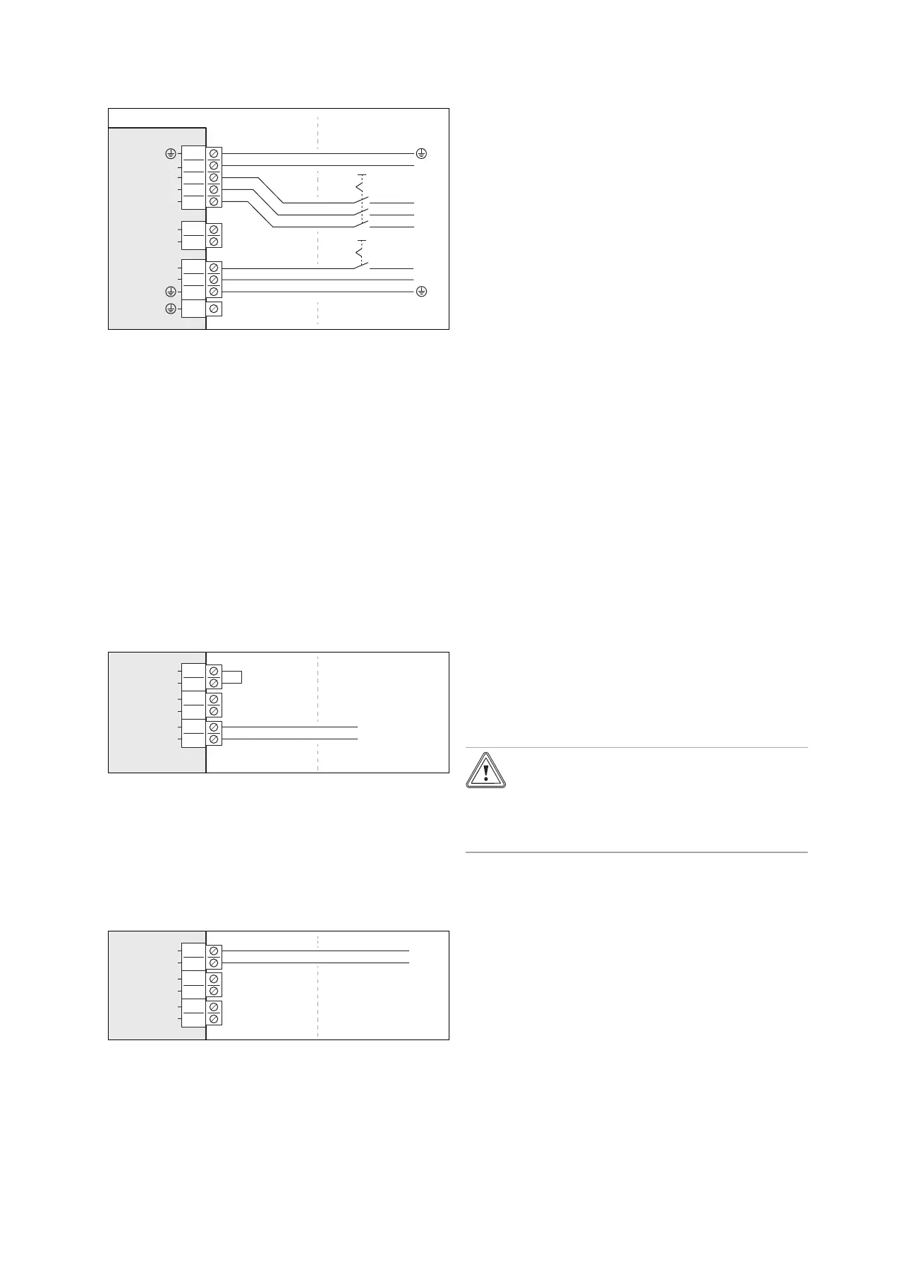
7.10 Connecting the eBUS line
1. Use a 2-pole eBUS line with a conductor cross-section
of at least 0.75 mm². Route this from the building and
through the wall duct to the product.
S20
S21
BUS
eBUS
+
-
5
6
3
4
1
2
X206
2. Connect the eBUS line to connection X206, BUS.
3. Use the strain relief clamp to secure the eBUS line in
place.
7.11 Connecting a limit thermostat
1. Use a 2-pole line with a conductor cross-section of
at least 0.75 mm². Route this from the building and
through the wall duct to the product.
2. Remove the bridge from the X206, S20 connection.
Connect the line here.
3. Use the strain relief clamp to secure the line in place.
7.12 Connecting accessories
▶ Observe the wiring diagram in the appendix.
7.13 Installing the cover for the electrical
connections
1. Note that the cover contains a safety-relevant seal
which must be effective in the case of a leak in the
refrigerant circuit.
2. Secure the cover by lowering it into the locking mechan-
ism without damaging the circumferential seal.
3. Use two screws to secure the cover to the lower edge.
8 Start-up
8.1 Checking before switching on
▶ Check whether all the hydraulic connections are estab-
lished correctly.
▶ Check whether all the electrical connections are estab-
lished correctly.
▶ Check, depending on the type of connection, whether
one or two disconnectors are installed.
▶
If it is stipulated for the installation site, check whether a
residual-current circuit breaker has been installed.
▶ Read through the operating instructions.
▶ After installation, ensure that at least 30 minutes have
passed before switching on the product.
▶ Ensure that the cover for the electrical connections is
installed.
8.2 Switching on the product
▶ Switch on all of the disconnectors to which the product is
connected in the building.
8.3 Checking and treating the heating
water/filling and supplementary water
Caution.
Risk of material damage due to poor-qual-
ity heating water
▶ Ensure that the heating water is of suffi-
cient quality.
▶ Before filling or topping up the installation, check the
quality of the heating water.
Checking the quality of the heating water
▶ Remove a little water from the heating circuit.
▶ Check the appearance of the heating water.
▶ If you ascertain that it contains sedimentary materials,
you must desludge the installation.
▶ Use a magnetic rod to check whether it contains mag-
netite (iron oxide).
▶ If you ascertain that it contains magnetite, clean the in-
stallation and apply suitable corrosion-inhibition meas-
ures, or fit a magnetic filter.
▶ Check the pH value of the removed water at 25 °C.
▶ If the value is below 8.2 or above 10.0, clean the installa-
tion and treat the heating water.
▶ Ensure that oxygen cannot get into the heating water.